i200 Series Scanners Image Processing Guide A-61520
Image Processing Guide for i200 Series Scanners Overview This documentation introduces concepts that may be new to many users. The Kodak i200 Series Scanners provide the ability to process scanned images to improve their quality. Using these features the scanner can sometimes make the scanned image look better than the original document. Basic image processing concepts are reviewed in this chapter to help you take advantage of these powerful features.
When you use the Kodak Scan Validation Tool, you will need to select which camera(s) you want to use to scan your document to get the desired results. You can use the following examples as a guide when making camera selections. Making camera selections When you launch the Kodak Scan Validation Tool, you will be making selections on the dialog boxes to set up your images for scanning test documents. Both TWAIN and ISIS have camera selection boxes that refer to the cameras within the scanners.
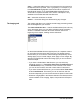
Starting the Scan Validation Tool 1. Select Start>Run or select Programs>Kodak>Document Imaging>Scan Validation Tool. Enter the filename or choose Browse to locate the ScanValidation.exe file. 2. Select TWAIN (or ISIS) for the Driver Type and the Kodak Scanner i200 as the Driver. The Scan Validation Tool dialog box will be displayed. 3. Double-click the Scanner icon to access the Kodak Scanner Properties dialog box.
Scan Validation Tool dialog box The Scan Validation Tool (SVT) is a diagnostic application that Kodak provides with most Kodak scanners. The SVT user interface allows access to all the features of the scanner and is a good way to verify that the scanner is working properly. The Scan Validation Tool allows you to verify scanner functionality using both the TWAIN Datasource and the ISIS Driver. Displays the user interface for the selected driver.
Using the TWAIN Datasource The TWAIN Datasource is a piece of software that communicates with your scanner. It is provided by Kodak with the i200 Series Scanners. Many scanning applications support the TWAIN standard and this datasource can be used to interface with these applications. This section provides descriptions of the scanner features using options on the TWAIN tabs and how to set these options. If you are using the TWAIN Datasource, follow the procedures in this section to set up your scanner.
Copy copies the settings of the front camera to the rear camera for the selected camera (bi-tonal, color or grayscale). For example, if you have Front Bi-tonal highlighted, these values will be copied to the Rear Bi-tonal camera. If you have Front Color highlighted, these values will be copied to the Rear Color camera. This option is only available for the Kodak i260 and i280 Scanners. OK saves the values set on all tabs. Cancel closes the dialog box without saving any changes.
Scanning bi-tonal images Bi-tonal images are scanned images that are made up of only blackand-white elements. The descriptions below are for bi-tonal images only. Binarization is the process of converting a grayscale or color image to a bi-tonal image. There are several different methods of performing this conversion. Two of the options are iThresholding and Adaptive Threshold Processing. These options are applied to grayscale scanned images and output a bi-tonal electronic image.
When Adaptive Thresholding is selected, Contrast values may range from 1 to 100. Fixed thresholding ATP disabled ATP enabled Fixed Processing used for black-and-white and other high contrast documents. A single level is set to determine the black-and-white transition. The threshold is programmable over the entire density range. Fixed thresholding sets Contrast to 0. If Fixed Processing is selected, Contrast is not available.
• Majority Rule sets the central pixel value in a matrix according to the majority of white or black pixels in a matrix. No Noise Filter Used Lone Pixel Image Filter used to enhance images containing dot matrix text and/ or images printed with shaded or colored backgrounds using halftone screens. This filter effectively eliminates noise caused by the halftone screen. Choose (none) or Halftone Removal.
Threshold used to convert a grayscale image to a bi-tonal image. The thresholding value is an integer ranging from 0 to 255. A low threshold value produces a lighter image, and can be used to subdue backgrounds and subtle, unneeded information. A high threshold value produces a darker image, and can be used to help pick up faint images.
Color Table Not applicable for bi-tonal images. See the next section “Scanning color images”. Paper Source — provides the following options: • ADF: select this option when using the scanner in continuous feed mode. • Flatbed: select this when using the flatbed for scanning documents that cannot be scanned when using the automatic document feeder, such as thick or bound documents (books).
Scanning color images The descriptions below are for scanning color images only. Resolution or dots per inch (dpi) indicates the scanning resolution, which largely determines the quality of the scanned image. The greater the resolution, the better the reproduction. However, scanning at a higher resolution also increases scanning time and file size. Choose a resolution value from the drop down list. The default is 200 dpi. Available resolutions are: 75, 100, 150, 200, 240, 300, 400 or 600.
Toggle Patch — the toggle patch is a type 4/toggle patch that is used to trigger the scanner to change from the current image stream (bitonal) to the alternative image stream (color/grayscale). This provides color-on-the-fly functionality for customers who choose to scan the majority of their documents bi-tonal with the option to switch to color/ grayscale and back when desired. When a toggle patch is detected, this determines the side(s) whose image output is toggled between bitonal and color/grayscale.
Scanning grayscale images The descriptions below are for scanning grayscale images only. Resolution or dots per inch (dpi) indicates the scanning resolution, which largely determines the quality of the scanned image. The greater the resolution, the better the reproduction. However, scanning at a higher resolution also increases scanning time and file size. Choose a resolution value from the drop down list. The default is 200 dpi. Available resolutions are: 75, 100, 150, 200, 240, 300, 400 or 600.
Toggle Patch — the toggle patch is a type 4/toggle patch that is used to trigger the scanner to change from the current image stream (bitonal) to the alternative image stream (color/grayscale). This provides color-on-the-fly functionality for customers who choose to scan the majority of their documents bi-tonal with the option to switch to color/ grayscale and back when desired. When a toggle patch is detected, this determines the side(s) whose image output is toggled between bitonal and color/grayscale.
The Paper tab The Paper tab allows you to define values relating to image output (i.e., cropping values, rotation, paper size and units of measure). Camera selection box lists the available sides of an image that you can define individual image processing values. The display window on the right will display the cropping area you are altering. The cropping area will change as values are being altered. Cropping values Cropping allows you to capture a portion of the document being scanned.
• Relative to Document: (zone processing): (used for batches of same-sized documents) — zone processing is a floating fixed crop window located relative to the upper left corner of a document. It allows you to select an area on the document to be delivered in either color/grayscale or bi-tonal format (a separate window for both bi-tonal and color/grayscale may be defined). Different parameters may be selected for both the front and rear of the image.
• Long Paper (i280 Scanner only): allows you to scan documents that exceed the 34-inch maximum length. You can scan documents that are up to 609 cm (20 feet) long at resolutions up to 300 dpi. These document types include document rolls (e.g., EKG charts, chart recorder rolls, and other roll-type documents). The scanned document is delivered in multiple image segments. Segment size is defined by entering the x and y offset values, width and length.
Overscan — allows you to add a specified value (inches/mm) before and after the edge of the image. Overscan values can be applied to the top and bottom of an image and/or the left and right of an image. Overscan is used in applications where automatic feeding of excessively skewed documents is likely. Overscan reduces the possibility of corner clipping on skewed images. Overscan can only be used with Fixed to Transport cropping.
The Compression tab Compression squeezes a file to decrease the total size. Bi-tonal images are normally compressed using a CCITT standard called Group IV, often used in conjunction with TIFF files. Color and grayscale images are often compressed using JPEG techniques. TIFF (Tagged Image File Format) is a file format standard commonly used for bi-tonal images. It is often used in conjuction with the CCITT Group IV compression standard to reduce image file size.
The following color/grayscale compression options are available: • JPEG — JPEG compression offers a JPEG quality of Draft, Good, Better, Best, Superior.
Filter Threshold the value that is used to identify the color which will be dropped out. This value is applied to the color area. Color with a Red/Green/Blue component more than the entered value is dropped. This setting determines how much of the selected color is dropped out. A lower value will leave more of the selected color in, while a higher value will drop more of the selected color out. Background this value will be substituted in the grayscale (prethresholded) image for the color being removed.
Document Ultrasonic Monitor — controls how aggressively the scanner will work to determine if more than one document is fed into the transport. You may set the Multi-Feed Detection to high, medium, or low sensitivity. If you disable Sensitivity, no detection will occur. NOTE: Regardless of the setting, Post-It™ notes will be detected as multi-fed documents.
The Options tab The Options tab allows you to set Image Transfer and Transport controls. Image Transfer Order if you are using simultaneous output scanning (bi-tonal and color/grayscale) for either side, this option controls the order in which the scanner returns image data. For example, if you are scanning color and bi-tonal and you select Bi-tonal Image, the scanner will return the bi-tonal front image, then the front color image. Transport Timeout allows you to set a transport timeout value.
The Printer tab The optional Kodak i200 Series Imprinter provides a vertical print capability that is programmed to support alphanumeric characters as defined by the host. It supports date, time, document count and custom messages. All print information is captured in a document header record. These printer controls and functions are accessed via the Printer tab. Enable — check this option to enable the Imprinter. Print String setup Print strings can be defined to match your application needs.
• Counter Format used to control the width of the document counter. Values range from 1 to 9. The following choices are available for printing the counter format. - Display leading zeros format (e.g., 0009) - Suppress leading zeros format (e.g., 9) - Compress leading zeros format (e.g., 9) • Date (in one of the following formats): MMDDYYYY, DDMMYYYY or YYYYMMDD. This format is defined in the Date Format field. • Date Delimiter select one of the date delimiters: Forward slash (/), hyphen (-), period (.
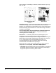
Y-Offset enter a value in this field to determine how far the printed information will appear from the leading edge of the document. The character top (“A” in the diagram below) points to the right edge of the document. The Y-Offset value can be set in Inches, Centimeters, Picas, 20th of Picas or Pixels. .35 in = Y offset A Start position Character top Printing area NOTE: Printing automatically stops 0.89 cm (.
The Setup tab The Setup tab allows you to download firmware and set the scanner clock. The Setup tab is only available when running the Scan Validation Tool, via the TWAIN Datasource. Package the scanner firmware runs your Kodak i200 Series Scanner. The value displayed in the Current field is the version of firmware currently in use by your scanner. Periodically Kodak releases updated versions of firmware which are available through Kodak Service and Support. Also check www.Kodak.com/go/DI.
The Info tab A-61520 April 2005 The Info tab displays information regarding your scanner. You can save this information that is displayed in the window to a file or refresh this information to redisplay current information from the save.
Using the ISIS Driver The ISIS Driver is a piece of software that communicates with the scanner. This driver is created and maintained by Pixel Translations, Inc. and is provided with the scanner by Kodak. Many scanning applications support ISIS drivers and this driver can be used to interface with them. This section provides descriptions of the options on the ISIS dialog boxes and how to set these options.
About displays the About dialog box. The About dialog box provides detailed information such as the driver version number, certification status and the version of QuickDriver used to develop this driver. Calibrate — the calibration process allows you to calibrate the scanner using the designated calibration target. When Calibrate is selected, the Calibrate dialog box is displayed. • Click OK to continue with the scanner calibration. Area displays the Scan Area dialog box.
Configure highlight the image you want to setup. As you select the image, other options will become available on the Scanner Settings dialog box. The availability of these options is dependent upon the selection you make. Convert Color to Grayscale this option is only available when configuring color cameras. When selected, the scanner will convert the color image data to grayscale before making it available to the host PC.
Cropping allows you to capture a portion of the document being scanned. All cropping options can be used with color/grayscale and binary images. Front and Rear cropping are independent, however, for simultaneous output scanning, color/grayscale and binary cropping must be the same per side. Only one cropping option can be assigned per image. Select one of the following options: • Fixed to Transport: (used for batches of same-sized documents) allows you to define the area or zone to be imaged.
This option may be used in conjunction with auto cropping where a separate color/grayscale or binary area to be saved is desired. It is useful in applications where a photograph, signature, embossment or seal appears in a consistent area for an application (you may want that small area in color/grayscale and the rest in binary). Original Bi-tonal image Relative to Document To define the zone, select Area to display the Scan Area dialog box.
Page layout The Page Layout area allows you to select paper size and viewing orientation. The default paper size is set when a scanner is first selected. You can choose a different paper size using the drop-down list box. Use the Scanner’s Maximum to enable auto cropping. NOTE: The Page Size and Page Layout selections also appear on the Scan Area dialog box. If you make a change on the Scanner Settings dialog box, the same selections will appear on the Scan Area dialog box and vice versa.
When using Adaptive Thresholding, Threshold and Contrast may be adjusted. Contrast values may range from 1 to 100. A Contrast value of 100 is considered fully adaptive thresholding. Fixed thresholding ATP disabled ATP enabled Dithering a method used to simulate gray levels. When selected, the Dithering options are available. • 64-Level Bayer Dither, 64-Level 45 Degree Clustered Dot Screen and 64-Level Dispersed Dot Screen: these represent alternative screening options to emulate gray.
Threshold used to convert a grayscale image into a binary (1 bit/ pixel) image. The thresholding value ranges from 0 to 255. The default is 90. A low threshold value will produce a lighter image, and can be used to subdue backgrounds and subtle, unneeded information. A high threshold value will produce a darker image, and can be used to help pick up faint images. Adjust the Threshold setting by dragging the Threshold sliding bar to the left or right to achieve the desired Threshold setting.
More Scanner Settings dialog box Additional image processing values unique to the i200 Series Scanners are available when you choose the More button on the Scanner Settings dialog box. Camera settings area The selections in the Camera area list the available sides (front and back) of an image where you can define individual image processing values. When starting the configuration process, use the steps below as a guide: 1. Check the images you wish to capture (Enable camera settings). 2.
Scan Source the host PC provides information to the scanner defining whether to scan one or both sides of the document. Simplex indicates that only one side (front side) of the document will be scanned. Simplex – Back indicates that only one side (rear side) of the document will be scanned. Duplex indicates that both sides of the document will be scanned. JPEG (Joint Photographic Editor Group) Quality.
Deskew check this option to automatically deskew a document within ±0.3 degrees of the leading edge of the document. Automatic deskew can detect up to a 45-degree skew and correct up to a 24degree angle at 200 dpi or a 10-degree skew angle at 300 dpi. This option is not available when you have Fixed to Transport or Relative to Document cropping selected. NOTE: To prevent data loss, the document must have all four corners within the image path.
• Majority Rule sets the central pixel value in a matrix according to the majority of white or black pixels in a matrix. No Noise Filter Used Lone Pixel Toggle Patch — the toggle patch is a type 4/toggle patch that is used to trigger the scanner to change from the current image stream (bitonal) to the alternative image stream (color/grayscale).
Color Dropout — electronic color dropout is used to eliminate a form’s background so that a document management system may automatically — through OCR (Optical Character Recognition) and ICR (Intelligent Character Recognition) technology — read pertinent data without interference from the lines and boxes of the form. You can select the desired dropout color, and alter the filter threshold and background. Electronic color dropout is available only for binary images.
Scanner Control dialog box Selecting the Scanner Control button on the More Scanner Settings dialog box displays the Scanner Control dialog box. This dialog box allows you to set multi-feed detection and transport control. The settings in this dialog box do not effect the quality of the image. See the section entitled, “Setting scanner controls” later in this document. OK saves the values set on the dialog box. Cancel closes the dialog box without saving any changes.
Ultrasonic Detection Sensitivity levels • Low Sensitivity: this setting is the least aggressive setting and is less likely to detect labels, poor quality, thick or wrinkled documents as multi-fed documents. • Medium Sensitivity: this is the default. Use Medium Sensitivity if your application has varying document thicknesses or labels attached to the document. Depending on the label material, most documents with labels should not be detected as a multi-fed document.
Defining the Scan area The Scan Area dialog box is only available for images when the Cropping option selected on the Scanner Settings dialog box is either Fixed to Transport or Relative to Document cropping. To access the Scan Area dialog box, select Area on the Scanner Settings dialog box.
The Scan Area dialog box allows you to define the amount of image data which is returned to the host. The area can be defined in Pixels, Inches or Centimeters. Page size and layout the default paper size is set when a scanner is first selected. You can choose a different paper size using the dropdown list box. NOTE: The Page Size and Page Layout selections also appear on the Scanner Settings dialog box.
EASTMAN KODAK COMPANY Document Imaging Rochester, New York 14650 www.kodak.com/go/docimaging Kodak is a trademark of Eastman Kodak Company.