USB-4718 8-Channel Thermocouple Input Module User Manual
Copyright The documentation and the software included with this product are copyrighted 2005 by Advantech Co., Ltd. All rights are reserved. Advantech Co., Ltd. reserves the right to make improvements in the products described in this manual at any time without notice. No part of this manual may be reproduced, copied, translated or transmitted in any form or by any means without the prior written permission of Advantech Co., Ltd. Information provided in this manual is intended to be accurate and reliable.
Product Warranty (2 years) Advantech warrants to you, the original purchaser, that each of its products will be free from defects in materials and workmanship for two years from the date of purchase. This warranty does not apply to any products which have been repaired or altered by persons other than repair personnel authorized by Advantech, or which have been subject to misuse, abuse, accident or improper installation.
CE This product has passed the CE test for environmental specifications when shielded cables are used for external wiring. We recommend the use of shielded cables. This kind of cable is available from Advantech. Please contact your local supplier for ordering information. Technical Support and Assistance Step 1. Visit the Advantech web site at www.advantech.com/support where you can find the latest information about the product. Step 2.
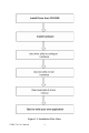
Contents Chapter 1 Introduction ..................................................... 2 1.1 1.2 1.3 Features ............................................................................. 2 Applications ...................................................................... 3 Installation Guide .............................................................. 3 1.4 Software Overview............................................................ 5 1.5 Chapter Figure 1.1:Installation Flow Chart ...............
3.2.2 3.2.3 Figure 3.1:I/O Connector Pin Assignment .................. 23 I/O Connector Signal Description ................................ 24 Table 3.1:I/O Connector Signal Description ............... 24 LED Indicator Status Description ................................ 24 Table 3.2:LED Indicator Status Description ................ 24 3.3 Analog Input Connections............................................... 25 3.4 Isolated Digital Input Connections.................................. 25 3.
CHAPTER 1 2 Introduction This chapter will provide information on the features of the DAS module, a quick start guide for installation, and some brief information on software and accessories for the USB-4718 Module.
Chapter 1 Introduction USB-4718 offers 8 thermocouple inputs with 16-bit resolution, up to 0.1% input range accuracy, or 4~20 mA inputs. Reliable and rugged enough for industrial applications, yet inexpensive enough for home projects, USB-4718 is the perfect way to add measurement and control capability to any USB capable computer. The USB-4718 is fully USB plug and play and easy to use. It obtains all required power from the USB port, so no external power connection is ever required. 1.
1.3 Installation Guide Before you install your USB-4718 module, please make sure you have the following necessary components: • USB-4718 DAS Module • USB-4718 User Manual • Shielded USB 2.0 cable (1.8 m) • Driver software Advantech DLL drivers (included in the companion CD-ROM) • Personal computer or workstation with a USB port (running Windows 2000, or XP) Some application software is also available for enhanced operation.
Figure 1.
1.4 Software Overview Advantech offers a rich set of DLL drivers, third-party driver support and application software to help fully exploit the functions of your USB-4718 module: • Device Drivers (on the companion CD-ROM) • LabVIEW driver • Advantech ActiveDAQ 1.4.1 Programming Choices for DA&C Module: You may use Advantech application software like Advantech Device Drivers.
1.5 Device Driver Programming Roadmap This section will provide a roadmap to demonstrate how to build an application from scratch using Advantech Device Drivers with your favorite development tools such as Visual C++, Visual Basic, Delphi, or C++ Builder. The step-by-step instructions on how to build your own applications using each development tool will be given in the Device Drivers Manual. Moreover, a rich set of example source code is also given for your reference. 1.5.
1.5.2 Programming with Device Drivers Function Library Advantech Device Drivers offer a rich function library that can be utilized in various application programs. This function library consists of numerous APIs that support many development tools, such as Visual C++, Visual Basic, Delphi and C++ Builder. 1.5.3 Troubleshooting Device Drivers Error Driver functions will return a status code when they are called to perform a certain task for the application.
USB-4718 User Manual 8
CHAPTER 2 2 Installation This chapter has a package item checklist, proper instructions about unpacking and step-by-step procedures for both driver and USB installation..
Chapter 2 Installation 2.1 Unpacking After receiving your USB-4718 package, please inspect its contents first. The package should contain the following items: • USB-4718 Module • Shielded USB 2.0 Cable (1.8 m) • Companion CD-ROM (DLL driver included) • User Manual The USB-4718 Module harbors certain electronic components vulnerable to electrostatic discharge (ESD). ESD could easily damage the integrated circuits and certain components if preventive measures are not carefully paid attention to.
2.2 Driver Installation We recommend you install the software driver before you install the USB-4718 module into your system, since this will guarantee a smooth installation process. The 32-bit DLL driver Setup program for the USB-4718 module is included on the companion CD-ROM that is shipped with your module package. Please follow the steps below to install the driver software: Step 1: Insert the companion CD-ROM into your CD-ROM drive.
Step4: Select the specific device and then just follow the installation instructions step by step to complete your device driver installation and setup. For further information on driver-related issues, an online version of the Device Drivers Manual is available by accessing the following path: Start\Programs\Advantech Automation \Advantech Device Manager\Device Driver’s Manual 2.
Figure 2.2: Device Manager Screen Note: If your module is properly installed, you should see the device name of your module listed on the Device Manager tab. If you see your device name listed, but marked with an exclamation sign “!” (Fig. 2-4), it means your module has not been correctly installed. In this case, remove the module from Device Manager by selecting its device name and press the Remove button. Then go through the driver installation process again.
Figure 2.3: USB-4718 Device Speed After your module is properly installed with your system, you can now configure your device using the Advantech Device Manager that has itself already been installed on your system during driver setup. A complete device installation procedure should include device setup, configuration and testing. The following sections will guide you through the Setup, Configuration and Testing of your device. 2.
2.4.1 Setting Up the Device Step 1: To complete the device setup and configuration procedures, you must first install the device along with its driver. (Please refer to the previous section of Chapter 2 for detailed installation instructions). Step2: You can view the device(s) already installed on your system (if any) in the Installed Devices list box. If you haven’t installed any devices, you might see a blank list. Figure 2.
"Restore" will reset device configurations to the factory settings. Note: Please refer to Appendix C for a detailed calibration procedure. Figure 2.5: The Device Setting Dialog Box 1.Board ID: Set the Board ID for easy identification. 2.Locate: The on-module LED indicator blinks when you continually press “Locate” button. 3.Label string: Edit the string label for identification purpose.
4.AI Channel setting: Set the thermocouple type/ analog input range for each AI channel. 5.Sample Rate adjustment: Drag the slide bar to adjust the sampling rate of your device. 6.Restore: Restore the AI Calibration setting or the CJC offset setting to default. (Restore Setting. Tif) 7.CJC Offset: Adjust CJC offset setting. (CJC Offset Adjustment. Tif) 8.AI Calibration: Analog input channel calibration function. Please refer to Appendix D for detailed operating guide. 2.4.
Table 2.1: Gain Code Gain Code (Hex) Type Range 0x08 Voltage 0-15mV 0x0A Voltage 0-50mV 0x0B Voltage 0-100mV 0x0D Voltage 0-500mV 0x0E Voltage 0-1.0V 0x0F Voltage 0-2.5V 0x8000 Current 0-20mA 0x8001 Current 4-20mA 2.5 Device Testing Following the Setup and Configuration procedures to the last step described in the previous section, you can now proceed to test the device by clicking the Test Button in the I/O Device Installation dialog window.
Figure 2.6: Analog Input Tab/Device Test Dialog 2.5.2 Testing Analog Output Function Unsupported on this module. Figure 2.
2.5.3 Testing Digital Input Function Click the Digital Input tab to show the Digital Input test panel as seen below. By the color of the LEDs, you can easily discern whether the status of each digital input channel is high or low. Red lamp: High Green lamp: Low Figure 2.8: Digital Input Tab/Device Test Dialog 2.5.4 Testing Digital Output Function Click the Digital Output tab to bring up the Digital Output test panel as shown below.
2.5.5 Testing Counter Function Unsupported on this module. Figure 2.10: Counter Tab Testing Unsupported Only after your module device is properly set up, configured and tested, can the device installation procedure be considered complete. After the device installation procedure is completed, you can safely proceed to the next chapter, Signal Connections. 2.
Figure 2.11: Unplug or Eject Hardware Dialog Step3: Select “Advantech USB4718 Device” and press “Stop” Button. Figure 2.12: Stop a Hardware device dialog box Step4: Unplug your USB device from the USB port. Note: Please make sure that you have closed the application programs before unplugging the USB device, otherwise some unexpected system errors or damages may happen.
CHAPTER 3 2 Signal Connections This chapter provides useful information on how to connect input and output signals to the USB-4718 via the I/O connectors..
Chapter 3 Signal Connections 3.1 Overview Maintaining good signal connections is one of the most important factors in ensuring that your application system is sending and receiving data correctly. A good signal connection can avoid unnecessary and costly damage to your PC and other hardware devices. 3.2 I/O Connectors USB-4718 is equipped with plug-in screw-terminal connectors that facilitate connection to the module without terminal boards or cables. 3.2.1 Pin Assignment Figure 3.
Figure 3.
3.2.2 I/O Connector Signal Description Table 3.1: I/O Connector Signal Description Signal Name Reference Direction Description IDI<0~7> ICOM Input Isolated Digital Input Channels ICOM -- -- Common Port of IDI Channels IDO<0~7> OCOM Output Isolated Digital Output Channels OGND -- -- Isolated Digital Output Ground OCOM -- -- Positive External Power Supply AI<0~7> -- Input Analog Input Channels CJC+/CJC- -- -- Cold Junction Compensation NC -- -- No connected 3.2.
3.2.4 3.2.4 Jumper Setting Description Table 3.
JP13: Watchdog Timer Setting The watchdog timer supervisory function will automatically reset USB4718 in the event of system failure. JP13 on USB-4718 can enable/disable watchdog timer function or reset module manually. Jumper Setting Description Enable watchdog timer function (Default setting) Disable watchdog timer function How to Reset USB-4718 Manually Plug the jumper to JP13 pin2-3 and then remove it, USB-4718 will reset. NOTE: Users may restart the application programs after USB-4718 is reset.
3.3 Analog Input Connections The differential input channels operate with two signal wires for each channel, and the voltage difference between both signal wires is measured. There are 8 analog input channels available on USB-4718 Figure 3.2: Differential Input Channel Connection 3.4 Isolated Digital Input Connections USB-4718 has 8 isolated digital input channels designated IDI0~IDI7. Each of isolated digital input channel accepts 5~30 VDC voltage inputs, and accept bi-directional input.
Figure 3.3: Digital Input Channel Connections 3.5 Isolated Digital Output Connections USB-4718 has 8 isolated digital output channels designated IDO0~IDO7. Each of isolated output channels comes equipped with a Darlington transistor. All 8 output channels share common collectors and integral suppression diodes for inductive loads. Figure 3-4 shows how to connect an external output load to the module’s isolated outputs.
Figure 3.4: Isolated Digital Input Channel Connections 3.6 Field Wiring Considerations • When you use USB-4718 to acquire data from outside, noises in the environment might significantly affect the accuracy of your measurements if due cautions are not taken. The following measures will be helpful to reduce possible interference running signal wires between signal sources and the USB-4718.
• If you have to place your signal cable parallel to a power line that has a high voltage or high current running through it, try to keep a safe distance between them. Or place the signal cable in a right angle to the power line to minimize the undesirable effect.
APPENDIX 2 Specifications A
Appendix A Specifications A.1 Analog Input Table A.1: Analog Input Channels Input type Input range Sampling rate 8 differential mV, V, and mA J, K, T, E, R, S and B Thermocouple Uni-polar 0~15mV, 0~50mV, 0~100mV, 0~500mV, 0~1V, 0~2.5V, 0~20mA, 4~20mA 10 samples/s(total) Accuracy ±0.1% or better (voltage and current input) Zero drift ±0.3 uV / °C Span drift ±25 ppm / °C CMR @ 50/60 Hz 92 dB Input impedance 1.8 M A.2 Accuracy for Thermocouple: Table A.
A.3 Isolated Digital Input Table A.3: Isolated Digital Input Channels Interrupt Inputs Optical Isolation Opto-isolator response time ESD Input Voltage Input Current 8 N/A 2500 VDC 25 µs 2,000 VDC VIH (max.) VIH (min.) VIL (max.) 10 VDC 12 VDC 24 VDC 30 VDC 30 VDC 5 VDC 3 VDC 2.9 mA (typical) 3.5 mA (typical) 7.2 mA (typical) 9.1 mA (typical) A.4 Isolated Digital Output Table A.
A.5 General Table A.5: General I/O Connector Type Removable 10-pin screw terminal x 4 Dimensions (LxWxH) 132 x 80 x 32 mm (5.2" x 3.2" x 1.3") Watchdog timer Yes Power requirements USB bus-powered Power Consumption 100mA @5V max.
B APPENDIX 2 Function Block
Appendix B Function Block USB-4718 User Manual 38
C APPENDIX 2 Firmware Download Utility
Appendix C Firmware Download Utility The firmware download utility can help you update your device’s firmware to the newest version to get the latest bug fixes and function improvements. Figure C.1: Install Firmware Download Utility Screen Note: After installation, the USB firmware download utility is located at C:\Program Files\Advantech\ADSAPI\Utilities by default. Note: You can get the newest firmware from Advantech’s website: www.advantech.
Step1 - Select Device: Launch the firmware download utility and press “Select…” button to choice the target device. You can check the working firmware version at the “Firmware Version” item. Figure C.2: USB Download Utility Step2 - Select Firmware File: Press “Load…” button to select the firmware. Figure C.
Step3 - Download Firmware: Press “Download” to start downloading the firmware to your target device. Then press “OK”, unplug your device and reinstall it to bring the new settings effective. Figure C.4: Firmware Download Completed.
Appendix D Analog Input Calibration
Appendix D Analog Input Calibration The following steps will guide you through the USB-4718 analog input channel software calibration. Please perform BOTH voltage and current input calibrating procedures to complete the calibration of USB-4718’s analog input channels. D.1 Voltage Input Calibration You need to calibrate only one channel (AI0). The other channels of USB-4718 will be calibrated automatically.
Figure D.1: USB-4718 Device Setting window Step 2: Select “0~0.015V” voltage input range (or any) and connect the 0V voltage source to AI0 of USB-4718, then click “Calibrate”. The information box will show up after the zero range calibration is completed. Then click “OK”.
Figure D.2: USB-4718 Calibration Wizard Figure D.3: Zero range calibration complete Step 3: Please start the full range calibration by connecting to the full range voltage source and click “Calibrate”.
Figure D.4: Full range calibration Figure D.5: Calibration Complete Step 4: Please repeat the procedures above to complete the other input ranges (0~0.050V/0~0.100V/0~0.500V/0~1.0V/0~2.5V) calibration.
D.2 Current Input Calibration You need to calibrate only one channel (AI0). The other channels of USB-4718 will be calibrated automatically. NOTE: Please make sure that the JP1 on USB-4718 is set to current input mode before you start voltage input calibrating. Step 1: Please follow the procedures of voltage input calibration but select the current input range setting in Calibration Wizard. Figure D.