ACP-7000 19" RACKMOUNT 7U HEIGHT INDUSTRIAL CHASSIS Users Manual i
Copyright This document is copyrighted, 2000, by Advantech Co., Ltd. All rights are reserved. Advantech Co., Ltd. reserves the right to make improvements to the products described in this manual at any time without notice. No part of this manual may be reproduced, copied, translated or transmitted in any form or by any means without the prior written permission of Advantech Co., Ltd. Information provided in this manual is intended to be accurate and reliable. However, Advantech Co., Ltd.
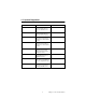
Table of Contents Contents Chapter 1 General Information ........................................1 1.1 1.2 1.3 1.4 1.5 1.6 Introduction ....................................................................... 2 Specifications .................................................................... 2 Passive Backplane Options ............................................... 3 Power Supply Options....................................................... 4 System Regulation..........................................
Figure 3.1: Alarm Board Layout ......................................... 26 3.2 3.3 3.4 Alarm board Specification .............................................. 27 Switch Setting ................................................................. 31 Thermal Sensor, LED, USB and K/B ............................. 32 Figure 3.2: Figure 3.3: Figure 3.4: Figure 3.5: Chapter Thermal Sensor................................................. 32 Thermal Sensor Layout.....................................
C H A PT E R 1 General Information 1 Chapter 1 General Information
Chapter 1 Introduction 1.1 Introduction ACP-7000 is a high performance, high capacity-computing platform which meets a variety of needs including filing, printing, applications, emails and Web server. This powerful departmental server includes a full Disk Array of high availability features for minimizing the system downtime especially in mission-critical CT application and factory management.
Operation Temperature:0°C ~ 40°C (32°F ~ 104°F) Storage Temperature: -40° to +60°C (-40° to +140°F) Relative Humidity: 10 ~ 95%@40°C, non-condensing Vibration (operating): 5Hz ~ 500Hz, 1G rams, 2G(non-operating) Shock (non-operating): 30 G with 11m Sec duration, 1/2 sine wave Altitude: 0 to 3048m (0 to 10,000 ft) Slide Rail:General Device C-300 series supported Safety: UL, cUL, CE 1.
1.4 Power Supply Options Model name Specification Watt Input Output Mini-load Safety MTBF PS400ATX-Z 400W ATX PFC 90/ 264Vac(F ull-range) +5V@ 42A+3.3V @20A+12 V@14A12V@1A5V@1A+5 Vsb@0.7 5A +5V@2A+ 12V@0.5 A+3.3V@ 0.2A UL/cULTUV 100,000 hours @25°C 75% load RPS460H-Z 460W ATX PFC 100 ~ 240 Vac(Fullrange) +5V@ 40A+3.3V @30A+12 V@27A12V@1A5V@0.8A +5Vsb@2 A +5 V @ 5 A+3.3 V @ 1A+12 V @ 2.5 A+5Vsb@ 0.
1.5 System Regulation Model name Specification Safety ACP-7000BP-00R Without backplane, without Power Supply(20-B/P version, for redundant power) - ACP-7000BP-00N Without backplane, without Power Supply(20-B/P version, for 2+1 or 3+1 power) - ACP-7000BP-46R With 460W ATX PFC Redundant Power Supply without backplane (20-Slot backplane version) UL.cULCE ACP-7000BP-57N With 570W ATX PFC 2+1 Redundant Power without backplane (20-Slot backplane version) UL.
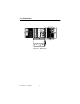
1.6 Dimensions Unit : mm [inch] Figure 1.
1.7 Exploded Diagram Figure 1.2: Exploded Diagram-1 Figure 1.
Figure 1.
C H A PT E R 2 System Setup 9 Chapter 2 System Setup
Chapter 2 System Setup 2.1 System Installation WARNING: Before starting the installation process, be sure to shut down all power from the chassis. Do this by turning off the power switch, and unplugging the power cord from the power outlet. When in doubt, consult with an experienced technician. 2.1.1 Attaching the handles. The handles for the front panel are in the accessory box. To install the handles, simply secure them to the front panel with the provided screws. 2.1.
2.1.3 Chassis Front and Rear Sections The front panel switches behind the door are used for system power, system reset 1, system reset 2 (option), alarm reset , power switch, USB and PS/2 keyboard. A multi-function key lock locks the door cover; user could lock the door cover by key or without key. System Reset 1 System Reset 2, Optional Alarm Reset Momentary Switch or Power On/Off Switch USB and PS/2 K/B Figure 2.2: Front Panel Switches Figure 2.
Figure 2.4: Rear View System Reset 1: Press this switch to reinitialize the system. This is the same as the hardware reset button. (Default setting) System Reset 2: Press this switch to reinitialize the second system. (Optional for dual system) Alarm Reset Switch: Press this switch to suppress or stop an audible alarm. Whenever a fault in the system occurs (e.g. fan failure, rising chassis temperature, backplane voltage problem), an audible alarm is activated.
The rear section of B/P version includes B/P rear window, 20-slot I/O brackets and the sheet metal kit for 1+1 or N+1 redundant power supply. The rear section of M/B version includes M/B rear window, 7-slot I/O brackets, ATX M/B I/O cover and sheet metal kit for single or 1+1 redundant power. 2.1.4 Drive Bay & SCSI Storage Installation The Standard Drive Bay of the ACP-7000 can hold a slim type CD-ROM, 5.25"(x2) and 3.5" (x1) devices Installation disk drives a. Remove the top cover b. c.
Figure 2.6: Driver Bay The SCSI storage holds six 3.5" mobile drawer which is for 1" height SCSI SCA-2 80-pin 3.5" HDD, and with 6-slot SCA backplane. User could install 1" height SCSI SCA-2 80-pin 3.5" HDD into this SCSI storage and use RAID card or RAID controller as RAID system for ACP7000 There is several type of SCSI 3.5" HDD, when in doubt, consult with an experienced technician before SCSI SCA-2 80-pin HDD installation. a. Open the front door by turning the key lock. b. Find the latch of 3.
The Latch has to be on upper location Figure 2.7: 3.5" Mobile Drawer Latch Figure 2.8: 3.
Figure 2.9: SCSI SCA-2 HDD Figure 2.10: Returning 3.5" Mobile Drawer 2.1.5 CPU Card and Add-on Cards Installation a. Open the top cover and move aside the cardholder by two screws b. Find out the location of PICMG slot, take out I/O bracket first, and install SBC(CPU card) c. Connect the 5Vsb and PS_ON cable of power supply to SBC. See Figure 2.11 d. Find the location of PCI or ISA slot, take out the I/O bracket first, and install add-on card. e.
5Vsb/PS_ON cable connect to SBC Figure 2.11: 5Vsb/PS_ON cable 2.1.6 ACP-7000BP-00R, ACP-7000BP-00N ACP-7000BP-00R has a momentary switch on the front panel. It is 20-slot backplane version but without backplane and power supply inside; it is with the mechanical design for 1+1 redundant power supply. ACP-7000BP-46R, see Figure 2.12, is without backplane; but with 460W 1+1 redundant power supply inside. ACP-7000BP-00N, all are same with ACP-7000BP-00R but with the mechanical design for N+1 redundant power.
Figure 2.13: ACP-7000BP-57N/81N Before starting to plug the power cord for ACP-7000BP-57N and ACP7000BP-81N, be sure both "Inlet" of power cord have the same direction to plug into to power outlet. See Figure 2.14 Figure 2.14: Power Inlet and Outlet 2.1.7 ACP-7000MB-00X, ACP-7000MB-00R ACP-7000MB-00X, has a momentary switch on the front panel and is for ATX M/B or two ways Server Board. It is without motherboard and power supply inside; and the mechanical design is for ATX single PS/2 type power supply.
7000MB-00X; but the mechanical design is for 1+1 redundant power supply. For ACP-7000MB-40Z, sees Figure 2.15, it is with 400W ATX PFC PS/2 single power supply. For the ACP-7000MB-46R, see Figure 2.16, you will understand it is with 460W 1+1 redundant power supply inside. Figure 2.15: ACP-7000MB-00X Figure 2.
2.2 LED Indicators 2.2.1 System Status LED The System Status LED shows as follows: LED Description RED GREEN or Orange PWR System Power Abnormal Normal HDD Hard Drive activity No light Data access TEMP Chassis Temperature Abnormal Normal FAN Cooling Fan status Abnormal Normal When the PWR LED is RED, it indicates a redundant power supply failure. To stop the alarm buzzer, press the Alarm Reset button.
2.2.2 Power Status LED The Power Status LED indicates the status of the backplane voltage signals. LED Description Light No light +3.3V +3.3V signal Normal No output +5V + 5V signal Normal No output +12V +12V signal Normal No output -5V - 5V signal Normal No output -12V -12V signal Normal No output When a LED fails to light, it indicates a problem with one of the voltage signals. An audible alarm is sounded.
Fan 5/Fan 6 Alarm Board C onnect w ith U 3 68-pin SCSI cable Connect with power supply Figure 2.17: SCSI Storage Cabling 2.4 Cooling Fan & Filter There are four (4) Cooling Fans located on the front of the chassis. The cooling fans are very easy to maintain since all of these four cooling fan are hot swappable, see Figure 2.18. There are two (2) cooling fans located inside chassis and on the rear of SCSI storage, these two cooling fans are with easy maintain design, see Figure 2.19.
Figure 2.18: System H/S Cooling Fans Figure 2.19: SCSI Storage Cooling Fans Figure 2.
Figure 2.
C H A PT E R 3 Alarm Board 25 Chapter 3 Alarm Board
Chapter 3 Alarm Board The alarm board is located under the cooling fan section. It gives an audible alarm when: a. Any power supply module of redundant power supply fails b. One of the cooling fans fai1s c. Temperature inside the chassis rises over 50°C(default setting) d. A problem occurs in one of the backplane voltage levels The detailed layout and specification of the alarm board are as follows: 3.1 Alarm board layout Figure 3.
3.2 Alarm board Specification Input Power: +5V, +12V Input Signals: • 7 FAN connectors (Pin 1: GND, Pin 2: +12V, Pin 3: FAN Signal) • One thermal board connector (it can connect up to 8 thermal boards in a roll) • One power good input • One alarm reset input. • One voltage signal connector (connect from back plane, includes ±12V, ±5V, 3.
CN2 : 10/100M LAN Connector Pin 1 : SPLED Pin 2 : TERMPLANE Pin 3 : RX+ Pin 4 : RX- Pin 5 : GND Pin 6 : LVCC Pin 7 : TX+ Pin 8 : TX- Pin 9 : LILED Pin 10 : TERMPLANE Pin 11 : N/A Pin 12 : NC CN4 : I2C Sensor board (LM75) Connector Pin 1 : +5V Pin 2 : Sensor board I2C bus clock Pin 3 : Sensor board I2C bus data Pin 4 : GND CN8 : RS-232 Connector Pin 1 : DCD Pin 2 : RX Pin 3 : TX Pin 4 : DTR Pin 5 : GND Pin 6 : DSR Pin 7 : RTS Pin 8 : CTS Pin 9 : RI Pin 10 : NC Pin 11 : NC Pin 12 : N/
Pin 17 : SPLED Pin 18 : NC Pin 19 : LILED Pin 20 : NC Pin 21 : GND Pin 22 : NC Pin 23 : TX+ Pin 24 : NC Pin 25 : TX- Pin 26 : NC Pin 27 : RX+ Pin 28 : NC Pin 29 : RXPin 31 : TERMPLANE Pin 30 : NC Pin 32 : NC CN12 : SNMP-1000 Daughter Board Connector (Right side) Pin 1 : NC Pin 2 : NC Pin 3 : Power Good A Pin 4 : NC Pin 5 : NC Pin 6 : NC Pin 7 : Diagnostic LED Pin 8 : FAN 1 Pin 9 : GND Pin 10 : FAN 2 Pin 11 : GND Pin 12 : FAN 3 Pin 13 : VCC Pin 14 : FAN 4 Pin 15 : VCC Pin 16 : FA
CN16 : 4 bit Power Good Input, Pin 1 : Power GOOD A Pin 2 : GND CN17 : Alarm Reset Pin 1: Reset Pin 2 : GND CN18 : LED Board Connector Pin 1 : GND Pin 2 : +5V Signal Pin 3 : +12V Signal Pin 4 : -5V Signal Pin 5 : -12V Signal Pin 6 : HDD Signal Pin 7 : Power Good Signal Pin 8 : Power Fail Signal Pin 9 : Temperature Good Signal Pin 10 : Temperature Fail Signal Pin 11 : Fan Good Signal Pin 12 : FAN Fail Signal Pin 13 : NC Pin 14 : +3.
3.
3.4 Thermal Sensor, LED, USB and K/B There is a temperature sensor inside the chassis, See Figure 3.2 to find the location and Figure 3.3 for the connection. When the temperature rises, the temperature sensor sends a signal to the alarm board and a continuous alarm is sounded. To stop the alarm, press the Alarm Reset Switch at the front panel. Pin Definition CN1~2: I2C Sensor board (LM75) Connector Pin 1: +5V Pin 2: Sensor board I2C bus clock Pin 3: Sensor board I2C bus data Pin 4: GND Figure 3.
There is a system LED indicator on the front door. See Figure 3.4 for the connection. Pin Definition CN1: LED Board Connector Pin 1: GND Pin 2: +5V Signal Pin 3: +12V Signal Pin 4: -5V Signal Pin 5: -12V Signal Pin 6: HDD 1 Pin 7: Power Good Signal Pin 8: Power Fail Signal Pin 9: Temperature Good Signal Pin 10: Temperature Fail Signal Pin 11: Fan Good Signal Pin 12: FAN Fail Signal Pin 13: HDD 2 Pin 14: +3.3V Signal Pin 15 : Option Figure 3.
CN1: Internal K/B Connector Pin 1: KBCK Pin 2: KBDT Pin 3: N/C Pin 4: GND Pin 5: KBVCC CN2: Internal USB Connector Pin 1: USBV0 Pin 2: USBD0- Pin 3: USBD0+ Pin 4: USBG0 Pin 5: GND Pin 6: USBV1 Pin 7: USBD1- Pin 8: USBD1+ Pin 9: USBG1 CN3: PS/2 Keyboard Connector CN4: USB Connector Figure 3.
C H A PT E R 4 Chapter 4 Ducks that Need Love! SCSI Storage 35 Chapter 4 SCSI Storage
Chapter 4 SCSI Storage 4.
Figure 4.1: SCA Backplane Layout 4.2 SAF-TE Stands for SCSI Accessed Fault-Tolerant Enclosure. The SCA backplane built-in GEM 318 which support SAF-TE provide a standard, non-proprietary way for third party disk and RAID controllers to be fully integrated with peripheral packing that supports status signals (LED's, audible alarm, LCD, etc), hot-swapping of hard drivers, and monitoring of enclosure components, such as disks, power supplies, temperature, fans, etc.).
4.3 RAID RAID stands for Redundant Array of Independent/Inexpensive Disks. ACP-7000 could be integrated with RAID card, such as AMI, Adaptec, Intel and Mylex RAID card to perform Disk Array operations. The RAID controller is also a suitable selection to integrate into ACP-7000 but be careful the length limitation. The max length of your RAID controller has to be under "240mm" to install into ACP-7000. See the figure 4.2 to watch out the limitation. 240 mm Figure 4.