ADAM-4570W 2-Port RS-232/422/485 to WLAN Data Gateway ADAM-4571W 1-Port RS-232/422/485 to WLAN Data Gateway User Manual
Copyright The documentation and the software included with this product are copyrighted 2005 by Advantech Co., Ltd. All rights are reserved. Advantech Co., Ltd. reserves the right to make improvements in the products described in this manual at any time without notice. No part of this manual may be reproduced, copied, translated or transmitted in any form or by any means without the prior written permission of Advantech Co., Ltd. Information provided in this manual is intended to be accurate and reliable.
Product Warranty (2 years) Advantech warrants to you, the original purchaser, that each of its products will be free from defects in materials and workmanship for two years from the date of purchase. This warranty does not apply to any products which have been repaired or altered by persons other than repair personnel authorized by Advantech, or which have been subject to misuse, abuse, accident or improper installation.
CE This product has passed the CE test for environmental specifications when shielded cables are used for external wiring. We recommend the use of shielded cables. This kind of cable is available from Advantech. Please contact your local supplier for ordering information. FCC Class B Note: This equipment has been tested and found to comply with the limits for a Class B digital device, pursuant to part 15 of the FCC Rules.
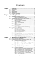
Contents Chapter 1 Overview .......................................................... 2 1.1 1.2 1.3 1.4 1.5 Chapter Introduction ....................................................................... 2 Features ............................................................................. 3 Specifications .................................................................... 3 Packing List....................................................................... 4 Ordering Information .......................
3.2.4 3.2.5 3.2.6 3.2.7 3.3 Figure 3.8:Network Config.Window-“Site Survey” .... 30 Port Configuration ....................................................... 31 Figure 3.9:Port Configuration Window ....................... 31 Security Configuration ................................................. 33 Figure 3.10:Security Configuration Window .............. 33 Status Messages .......................................................... 34 Figure 3.11:Status Messages ........................................
CHAPTER 1 2 Overview This chapter provides an overview of ADAM-4570W and ADAM-4571W.
Chapter 1 Overview 1.1 Introduction ADAM-4570W and ADAM-4571W are cost-effective data gateways between RS-232/422/485 and 802.11b Wireless LAN interfaces. They provide a quick and low-cost method to connect any RS-232/422/485 device to 802.11b wireless LAN. Functionally transparent and efficient, ADAM-4570W and ADAM-4571W saves costs when existing hardware and software must continue to be used.
1.2 Features • Supports 802.11b standard • Supports Wireless LAN Ad-Hoc and Infrastructure modes • Supports high transmission speeds up to 230 kbps • Supports an advanced security mechanism to avoid unauthorized access • Auto-reconnection • Remote download of firmware • Auto-detection • Easily-managed Port Mapping Utility • Supports Windows 98/NT/2000/XP driver • Surge protection for RS-485 line and power supply • Automatic RS-485 data flow control 1.3 Specifications • Protocol: TCP/IP • Network: 802.
• Power Requirement: Unregulated 10 ~ 30 VDC • Power Consumption: Max @ 4 W • Mounting: DIN-rail, panel mounting, piggyback stack • Operating Temperature: 0 ~ 55° C (32 ~ 131° C) • Storage Temperature: -20 ~ 80° C (-4 ~ 176° C) • Operating Humidity: 20 ~ 95% (non-condensing) • Storage Humidity: 0 ~ 95% (non-condensing) 1.4 Packing List Before setting up the system, check that the items listed below are included and in good condition.
CHAPTER 2 2 Getting Started In this chapter, you will be given an overview of hardware installation procedure for ADAM-4570W and ADAM-4571W. As mentioned in the previous chapter, ADAM-4570W and ADAM-4571W comes ready for all network connections, including WLAN and RS-232/422/485 port connections..
Chapter 2 Getting Started 2.1 Installation Procedure Overview See the flow chart below for a brief overview of the installation procedure. Figure 2.
2.2 Understanding ADAM-4570W & ADAM-4571W ADAM-4570W and ADAM-4571W are advanced data gateway units. They extend traditional COM ports of a PC by giving them access to an 802.11b WLAN network. Since ADAM-4570W and ADAM-4571W are connected through an 802.11b WLAN network, you will need to know some basic facts about networking in order to get the server hooked up correctly. 2.2.
The following illustration shows a typical network architecture: Figure 2.
2.2.2 LED Definitions There are network status LEDs located on the top panel of ADAM4570W and ADAM-4571W. ADAM-4570W has five, while ADAM4571W has four. Each has its own specific function. Table 2.
2.2.3 Labels To make it easier to remember the relevant IP addresses of your application, we have provided five labels. Use these to note information like where the host PC is mapped to the ADAM-4570W or ADAM-4571W port, and place it in a secure location. Examples: 172.18.1.59: The IP address of specific ADAM-4570W. 160.59.20.89: The IP address of specific host PC mapped to this port. Figure 2.3: Sticker 2.2.
In the same way, there are two kinds of BSS -- infrastructure mode and ad hoc mode -- exist in Diagnostic Mode. Table 2.2 shows how to enter the mode you want by adjusting the switch. Table 2.
2.3 Connecting the Hardware Next, we will explain how to mount your ADAM-4570W /ADAM4571W module, and then how to connect to the WLAN network, hook up the power cable, and connect the ADAM-4570W/4571W’s serial port to serial devices. Note: If you are planning to install other communication cards, we recommend that this is done before the ADAM module is installed. 2.3.
DIN Rail Mounting You can mount ADAM modules on a standard DIN Rail. First, using two screws, attach the DIN rail bracket to the ADAM module. Because the screw heads are flat, the top of the screws will be even with the module’s front panel surface. You can now snap the ADAM module to a DIN rail. Figure 2.
Piggyback Stack ADAM modules can be stacked as shown in the figure below. Figure 2.6: Piggyback Stack 2.3.2 Wireless Connection ADAM-4570W and ADAM-4571W operate in the 802.11b WLAN environment, which is created by an access point working with 802.11b protocols. Locate your access point and connect to the Ethernet network first. Then build up the connection between the access point and the ADAM-4570W/4571W (Refer to Appendix A "Quick Start").
Power Connection You should take the following steps to connect power to the ADAM module. 1. Connect the power cable to the 2-pin connector. 2. Connect the power cable to the power adapter. Figure 2.7: Power Connection for ADAM-4570W/4571W If ADAM-4570W / ADAM-4571W are working properly, the green power LED will be lit.
2.3.3 Serial Connection ADAM-4570W has two, while ADAM-4571W has one RJ-48 serial port phone jack on the bottom. You may use the supplied RJ-48 to DB9 cable to connect your serial device. Simply plug the RJ-48 end of the cable into the jack, and plug the DB9 end into the serial connector of the serial device. The pin assignment of the RJ-48 to DB-9 cable is shown in the table below. Table 2.
CHAPTER 3 2 Installation & Configuration This chapter first guides you in the installation of drivers and software utilities, and then shows how to use the software utilities.
Chapter 3 Installation & Configuration 3.1 Driver and Utility Installation In order to use a PC via an Ethernet network to control serial devices connected to ADAM-4570W or ADAM-4571W, you must first have a host running Windows 98/NT/2000 or XP. You also need the host to have an Ethernet card and TCP/IP protocol installed. Following are the installation instructions to set up ADAM-4570W / ADAM-4571W. 1. Insert the Advantech INET SERIES DRIVER UTILITY CD-ROM into the CD-ROM drive (e.g. D:\) on the host PC.
3.2 Configuring EDG Series-ADAM-4570W/4571W ADAM-4570W and ADAM-4571W are part of Advantech’s EDG Series. All products in the EDG series provide easy Windows configuration through an Ethernet or WLAN connection and the ‘Configuration Utility’ program. ‘Configuration Utility’ can automatically find all compatible devices on a network for easier configuration of parameters for TCP/IP.
Figure 3.1: Locate All EDG Series Or select a group of ADAM-4570 with these steps. 1. Select “Designated” and then “ADAM-4570”, and last “Locate”. 2. The “Status” LED of all “ADAM-4570” on the LAN will be lit. Figure 3.
Of course, you can select just one ADAM-4570W if you like. When you select a specific device, the LED that stands for “Status” will be lit for 8 minutes. If you select another device, the “Status” LED of the first selected device will turn off. Figure 3.
3.2.2 System Configuration ‘Configuration Utility’ can only search for EDG devices on the local network and not beyond a router or gateway. Make sure that all EDG devices that you want to monitor reside on the same local network as the host PC. Figure 3.4: System Configuration Window Device Name ‘Configuration Utility’ provides default names for the devices it finds on the network. This is to distinguish the EDG devices from each other.
Firmware Version In this field, ‘Configuration Utility’ shows the firmware version of the EDG device. You might need to refer to the firmware version to determine what functions are available on the EDG device. In case there are problems concerning the firmware version, please provide the version number to our customer service. 3.2.3 Network Configuration Figure 3.5: Network Configuration Window-General Wireless Firmware Here is the firmware version of the wireless module embedded in the ADAM-4570W/4571W.
Region Set the region. Each region has its default channel range. When you choose a specific region, the optional channel range and numbers in the below drop-down menu will be changed automatically. • General (USA and Canada): 1~11 • Europe (except for France and Spain): 1~13 • France: 10~13 • Spain: 10~11 • Japan: 14 only • Japan Wide: 1~14 For other regions, please choose General, or refer to table 3.1 to find an acceptable frequency.
Channel Each region has its default channel range, which is decided by each region’s telecommunications laws. Table 3-1 shows the corresponding frequency of channels. If you wish to setup two networks, it is recommended that you use channels that are not close to each other to minimize interference. Table 3.1: Channel and Frequency Corresponding Table Channel Frequency(GHz) 1 2.412 2 2.417 3 2.422 4 2.427 5 2.432 6 2.437 7 2.442 8 2.447 9 2.452 10 2.457 11 2.462 12 2.467 13 2.
SSID The SSID (Service Set Identity) identifies a specific wireless LAN. Before associating with a particular wireless LAN, a station must have the same SSID as its access point. That means the user must set the specific access point’s SSID in infrastructure networks, or set the same SSID in ad hoc networks. If the user doesn’t know which access point is the most appropriate one, just set “ANY” for an automatic search. The frame on the right appears with the current associated AP’s MAC address and SSID.
The “Advanced” drop-down menu identifies several parameters that are related to the 802.11b wireless network. We suggested the default settings are not changed unless necessary. Table 3.2: Advanced Parameters’ Default Value and Range Parameters Default Value Range Beacon Interval 100 0~65535 RTS Threshold 2347 0~2347 Fragment Threshold 2346 256~2346 Preamble Long Long/Short Beacon Interval In infrastructure networks, the access point periodically sends beacons.
RTS Threshold RTS Threshold is the frame size above that an RTS/CTS handshake will be performed before attempting to transmit. RTS/CTS asks for permission to transmit to reduce collisions, but adds considerable overhead. Disabling RTS/CTS can reduce overhead and latency in WLANs where all stations are close together, but can increase collisions and degrade performance in WLANs where stations are far apart and unable to sense each other to avoid collisions.
Figure 3.7: Network Configuration Window-“Authentication” WEP Authentication Type WEP (Wired Equivalent Privacy) is a kind of standard to encrypt the data frame. • Open system: No encryption for network communication. You can neglect the key setting on the right side. • WEP Share Key: Both communication devices use the same key as encryption. • Automatic: Detect the WEP situation of the access point automatically. ADAM-4570W/4571W will use the current key for encryption.
Key Index This lists the supported encryption keys that you can choose from. Key Format Set the key format. Table 3.3 shows the allowed characters and length of the different key index and key formats. Table 3.3: Key Setting Index Alphanumeric Hexadecimal 64 bits Up to 5 random characters on the keyboard Up to 10 random hexadecimal characters (0 ~ 9, a ~ f) 128 bits Up to 13 random characters on the keyboard Up to 26 random hexadecimal characters (0 ~ 9, a ~ f) Figure 3.
3.2.4 Port Configuration Figure 3.9: Port Configuration Window Name Select which port on the EDG device is to be connected to the serial device. Description You can give a more detailed description on the function of the port for easier management and maintenance. Descriptions have a limit of 128 characters. Type The EDG device offers three kinds of serial protocols, RS-232, RS-485 and RS-422. You can use any of the three serial protocols according to your requirements.
Flow Control The EDG device provides four options: None, Xon/Xoff, RTS/CTS, DTR/DSR. Data Bits The EDG device provides four options: 5, 6, 7 or 8. Stop Bits The EDG Series provides three options: 1, 1.5 or 2. Baud Rate The EDG Series supports baud rates from 50 to 230,400bps. Host Idle Timeout With ADAM-4570W and ADAM-4571W, ‘Configuration Utility’ allows setting of the host idle timeout value.
3.2.5 Security Configuration Figure 3.10: Security Configuration Window Only configure the authorized IP This option is enabled in order to protect all configuration settings from being changed inadvertently. Allow any IP to access If this option is enabled, any PC can access data from this EDG device. The specified IP which can access If you want to restrict access to certain PCs, you can list their IP addresses in this area. The limit is 32 PCs.
3.2.6 Status Messages The status messages shown at the bottom of the utility window reflects the current status of the EDG device. Figure 3.11: Status Messages Read The configuration utility has found the EDG device and is ready for use. Searching EDG COM port The configuration utility is searching for EDG devices. Querying DATA from EDG COM port The configuration utility is getting data from the EDG device.
Lost Connection from the Device Due to device shut down or network failure, the configuration utility has lost connection after 5 seconds. Fail to apply this setting to the device Your settings are not accepted by the EDG device. The device fails to respond The connected device does not respond. Fail to reset the device Fail to reset the EDG device. 3.2.
3.3 Port Mapping Utility The purpose of ‘Port Mapping Utility’ is to help you manage all serial ports that are in one Windows-based PC. The utility displays three types of ports: Used ports, Unused ports and EDG device ports. Please follow the steps below. 1. Click the “Unused Ports” item and select the port that you want to configure. Figure 3.
2. Click the “Add” button to assign a COM port to a specific EDG device. Figure 3.13: Assign COM Port to EDG Series 3. Type the IP address of the EDG device and select ports. Figure 3.14: Warning Window Note: You can not assign two virtual COM ports to the same EDG port. If this happens, a dialog box will appear to warn you. 4.
5. If you want to remove the COM port connection, click “Delete” to remove it. Figure 3.15: Remove COM port 6. After you complete the configuration, click ”Apply” . 3.3.1 Self Test Function The purpose of this test is to make sure the communication from host PC to ADAM-4570W/4571W is OK. If there is still an error, you can check the communication from the ADAM-4570W/4571W to the serial devices.
1. Click the Test button in ‘Port Mapping Utility’. Figure 3.16: Test Window Signal Test • RTS -> CTS Check the RTS and CTS signals between two ports • DTR -> RI Check the DTR and RI signal between two ports • DTR -> DSR Check the DTR and DSR signal between two ports • DTR -> DCD Check the DTR and DCD signal between two ports Communication Parameters Test • Baud rate 50 bps ~ 230.4 kbps • Data bit 5, 6, 7, 8 • Stop bit 1, 1.
1.Click the OK button to return to the port mapping window. All the ports in the EDG Series are tested ok. Figure 3.17: Loopback Test 3.3.2 Upgrading Firmware Advantech continually upgrades its firmware to keep up with the everexpanding world of computing. You can use the download function located in ‘Port Mapping Utility’ to carry out the upgrade procedure. Please access Advantech’s Web site at http://www.advantech.com to download the latest version of the firmware.
1. Click on the Update FW button. Figure 3.18: Firmware Update Window 2. Select the firmware you want to update. Figure 3.
3. After downloading the firmware completely, click on the Reboot button. The EDG device will restart automatically. Figure 3.20: Download and Update Firmware Note: After clicking the Reboot button, the configuration utility will not reboot the EDG device before all applications stop accessing the EDG device. 3.3.3 Save the Configuration You can save or recover the configuration via the File menu. Figure 3.
3.3.4 Auto-Reconnection Function Sometimes, the system may crash because the EDG device is interrupted or powered-off by accident. You would want the host PC to reconnect to the EDG device automatically after such an occurrence. The EDG device provides an “Auto-reconnect” function to solve this problem. If the EDG device is powered-off accidentally, the driver will keep trying to reconnect the EDG Series automatically.
ADAM-4570W & 4571W User Manual 44
CHAPTER 4 2 Troubleshooting This chapter explains how to solve some of the most common problems you could encounter while using ADAM-4570W or ADAM-4571W. If you are still having problems after reading this chapter, contact your dealer, or e-mail Advantech support for help.
Chapter 4 Troubleshooting Configuration Utility can not find ADAM-4570W/4571W 1. Check POWER LED. If it is off, you have to check the following: • Make sure the EDG device’s power cable is plugged in, and the server is receiving power. • Check that the server’s network connector is plugged in properly. • Make sure your computer is properly connected to the network. • Make sure the input voltage is between +10 and +30 V 2. Check LINK LED.
The host PC can access the EDG device at a local site, but after moving the EDG device to a remote site, the PC can no longer access it. Due to differing network interface connections, your dynamic IP address might have changed, and as a result, you are no longer on the ADAM4570W/4571W’s access control list. To resolve this issue: 1. Confirm the new IP address of the EDG device. 2.
ADAM-4570W & 4571W User Manual 48
APPENDIX A 2 Quick Start
Appendix A Quick Start There are two ways to complete the wireless connection between an access point and ADAM-4570W/4571W; via Diagnostic Ad hoc Mode or via Diagnostic Infrastructure Mode. We recommend you use Ad Hoc if your host PC is equipped with a wireless module. A.1 Diagnostic Ad hoc Mode (with wireless module) 1. Set the switch of ADAM-4570W/4571W to Diagnostic Mode, then power on. 2. Wait for 10 to 20 seconds until the signal quality is stable. 3.
5. Connect to WLAN BSS, and check the configuration information to make sure the connection is O.K. 6. Start the Configuration Utility tool on your host PC, and find the ADAM-4570W/4571W. You can see the default setting below.
7. Reset the Network setting as needed. (About Network setting, please refer to section 3.2.3 of the manual) Power off ADAM-4570W/4571W, adjust the switch to Normal Mode, then reboot it to finish the wireless connection. Now you can configure and set up port mapping through the access point (You can connect to the access point by WLAN or Ethernet).
A.2 Via Diagnostic Infrastructure Mode (without wireless module) 1. Set the switch of ADAM-4570W/4571W to Normal Mode, then power on. 2. Wait for 10 to 20 seconds until the signal quality is stable. 3. Adjust the switch to Diagnostic Mode, then wait for 5 seconds until the signal quality is blinking. 4. Return the switch to Normal Mode , then ADAM-4570W/4571W will reboot automatically with Diagnostic Infrastructure Mode.
ADAM-4570W & 4571W User Manual 54
B APPENDIX 2 Compatible Access Points
Appendix B Compatible Access Points The table below shows compatible access points for ADAM wireless products. Item Brand Model Standard 1 CISCO Aironet 1100 series AIR-AP1T21G-A 802.11b/g 2 3COM 3CRTRV10075/WL-534 802.11b/g 3 D-Link DI-514 802.11b 4 ASUS WL-330G 802.11b/g 5 ZCOM XI-1450 802.