AIMB-554 Socket 479 Intel Core™ 2 Duo/Core™ Duo/Core™ Solo Processor-based 533/667 MHz FSB Micro ATX Motherboard with PCI-E/ DDR2/Dual GbE LAN User Manual
Copyright This document is copyrighted, 2006, by Advantech Co., Ltd. All rights are reserved. Advantech Co., Ltd. reserves the right to make improvements to the products described in this manual at any time without notice. No part of this manual may be reproduced, copied, translated or transmitted in any form or by any means without the prior written permission of Advantech Co., Ltd. Information provided in this manual is intended to be accurate and reliable. However, Advantech Co., Ltd.
A Message to the Customer Advantech Customer Services Each and every Advantech product is built to the most exacting specifications to ensure reliable performance in the harsh and demanding conditions typical of industrial environments. Whether your new Advantech equipment is destined for the laboratory or the factory floor, you can be assured that your product will provide the reliability and ease of operation for which the name Advantech has come to be known. Your satisfaction is our primary concern.
Certifications This device complies with the requirements in part 15 of the FCC rules: Operation is subject to the following two conditions: • This device may not cause harmful interference • This device must accept any interference received, including interference that may cause undesired operation This equipment has been tested and found to comply with the limits for a Class A digital device, pursuant to Part 15 of the FCC Rules.
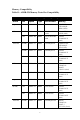
Memory Compatibility Table1.1: AIMB-554 Memory Tested for Compatibility Table 1.1: AIMB-554 Memory Tested for Compatibility Brand Size Speed Type Part Number Memory Apacer 1GB DDR2 533 DDR2 78.01066.
Table 1.1: AIMB-554 Memory Tested for Compatibility Brand Size Speed Type Part Number Memory (RoHS) 512MB DDR2 533 DDR2 TS64MLQ64V5J SEC K4T51083QC (64X8) 1GB DDR2 533 DDR2 TS128MLQ64V5J SEC K4T51083QC (64X8) 512MB DDR2 667 DDR2 TS64MLQ64V6J SEC K4T51083QC ES (64x8) 512MB DDR2 667 DDR2 TS64MLQ64V6J Micron 5XB32D9DCL (64x8) 1GB DDR2 667 DDR2 TS128MLQ64V6J SEC K4T51083QC ES (64x8) Network Feature Comparison Table 1.
Product warranty Advantech warrants to you, the original purchaser, that each of its products will be free from defects in materials and workmanship for two years from the date of purchase. This warranty does not apply to any products which have been repaired or altered by persons other than repair personnel authorized by Advantech, or which have been subject to misuse, abuse, accident or improper installation. Advantech assumes no liability under the terms of this warranty as a consequence of such events.
Initial Inspection Before you begin installing your motherboard, please make sure that the following materials have been shipped: • AIMB-554 Socket 479 Intel Core™ 2 Duo/Core™ Duo/Core™ Solo Processorbased Industrial Micro-ATX Motherboard • 1 AIMB-554 startup manual • 1 CD with driver utility and manual • 1 FDD cable P/N: 1700340640 • 1 Ultra ATA 66/100 HDD cable P/N: 1701400452 • 2 Serial ATA HDD data cable P/N: 1700071000 • 2 Serial ATA HDD power cable P/N: 1703150102 • 1 ATX 12V power
Contents Table 1.1:AIMB-554 Memory Tested for Compatibilityv Chapter 1 Hardware Configuration .................................2 1.1 1.2 1.3 Introduction ....................................................................... 2 Features ............................................................................. 3 Specifications .................................................................... 3 1.3.1 1.3.2 1.3.3 1.3.4 1.3.5 1.3.6 1.3.7 1.4 System....................................................
2.3 2.4 2.5 2.6 2.7 2.8 2.9 2.10 2.11 2.12 Floppy Drive Connector (CN3)....................................... 19 Parallel Port (CN4).......................................................... 20 USB Ports (CN6, CN63, CN31, CN32) .......................... 20 VGA Connector (CN7) ................................................... 21 Serial Ports (COM1:CN9; COM2:CN10) ....................... 21 PS/2 Keyboard and Mouse Connector (CN11) ............... 22 External Keyboard & Mouse (CN12) ......................
3.3 Standard CMOS Setup .................................................... 41 3.3.1 3.3.2 3.3.3 3.3.4 3.3.5 3.3.6 3.4 Advanced BIOS Features ................................................ 43 3.4.1 3.4.2 3.4.3 3.4.4 3.4.5 3.4.6 3.4.7 3.4.8 3.4.9 3.4.10 3.4.11 3.4.12 3.4.13 3.4.14 3.4.15 3.4.16 3.4.17 3.5 Date............................................................................... 41 Time ..............................................................................
3.5.16 3.5.17 3.5.18 3.5.19 3.6 Integrated Peripherals...................................................... 49 3.6.1 3.6.2 3.6.3 3.6.4 3.6.5 3.6.6 3.6.7 3.6.8 3.6.9 3.6.10 3.6.11 3.6.12 3.6.13 3.6.14 3.6.15 3.6.16 3.6.17 3.6.18 3.6.19 3.6.20 3.6.21 3.6.22 3.6.23 3.6.24 3.6.25 3.7 DVMT / FIXED Memory Size ..................................... 48 Boot Display ................................................................. 48 Panel Number ...............................................................
3.7.8 3.7.9 3.7.10 3.7.11 3.7.12 3.7.13 3.7.14 3.7.15 3.7.16 3.7.17 3.8 PnP/PCI Configurations .................................................. 58 3.8.1 3.8.2 3.8.3 3.8.4 3.9 Figure 3.12:PnP/PCI configurations screen.................. 58 Reset Configuration Data.............................................. 58 Resources Controlled By .............................................. 58 PCI / VGA Palette Snoop ............................................. 58 Maximum Payload Size ..........................
Chapter 7 LAN Configuration ........................................82 7.1 7.2 7.3 7.4 Introduction ..................................................................... 82 Features ........................................................................... 82 Installation....................................................................... 82 Win XP Driver Setup (Intel 82573) ................................ 83 Appendix A Watchdog Timer.............................................86 A.
B.16 HDD LED Connector (CN19)....................................... 107 B.17 ATX Soft Power Switch (CN21) .................................. 107 B.18 H/W Monitor Alarm (CN22)......................................... 108 B.19 SM Bus Connector (CN29) ........................................... 108 B.20 USB/LAN ports (CN31 and CN32) .............................. 109 Table B.16:HDD LED Connector (CN19) ................. 107 Table B.17:ATX Soft Power Switch (CN21) ............. 107 Table B.
CHAPTER 1 General Information 1
Chapter 1 Hardware Configuration 1.1 Introduction The AIMB-554 is designed with the Intel® 945GM and the ICH7M-DH for industrial applications that require both high-performance computing and enhanced power management capabilities. The motherboard supports Intel Core™ 2 Duo/Core™ Duo/Core™ Solo Processor up to 2.16GHz with 533/667 MHz front side bus and DDRII 400/533/667 MHz memory up to 2 GB.
1.2 Features • PCI Express architecture: Designed with the Intel 945GM and ICH7M-DH PCI-Express chipset, the AIMB-554 has dual/single Gigabit LAN via PCI-E x1 bus, 1 PCI-E x 16 slot and 1 PCI-E x 4 slot. • High Performance I/O Capability: Dual/single Gigabit LAN via PCIE x1 bus, 2 PCI 32-bit/33MHz PCI slots, 2 SATA connectors and 8 USB 2.0 ports.
devices with software Serial ATA RAID 0,1. One on-board IDE connector supporting up to two enhanced IDE devices. Supports PIO mode 4 (16.67MB/s data transfer rate) and ATA 33/66/100 (33/66/100MB/s data transfer rate.) BIOS enabled/disabled. • Floppy disk drive interface: Supports one floppy disk drive, 5¼" (360 KB and 1.2 MB) or 3½" (720 KB, 1.44 MB). BIOS enable/disable 1.3.2 Memory • RAM: Up to 2 GB in four 240-pin DIMM sockets. Supports dual-channel DDRII 400/533/667 SDRAM. 1.3.
1.3.5 Ethernet LAN • Supporting single/dual 10/100/1000Base-T Ethernet port(s) via PCI Express x1 bus which provides 500 MB/s data transmission rate. • Controller: LAN 1: Intel® 82573 (G2 version or VG version) LAN 2: Intel® 82573 (G2 Version) 1.3.6 Industrial features • Watchdog timer: Can generate a system reset or IRQ11. The watchdog timer is programmable, with each unit equal to one second or one minute (255 levels) 1.3.
1.4 Jumpers and Connectors Connectors on the AIMB-554 motherboard link it to external devices such as hard disk drives and a keyboard. In addition, the board has a number of jumpers used to configure your system for your application. The tables below list the function of each of the board jumpers and connectors. Later sections in this chapter give instructions on setting jumpers. Chapter 2 gives instructions for connecting external devices to your motherboard. Table 1.
Table 1.
1.5 Board Layout: Jumper and Connector Locations CN32 CN31 CN55 CN7 CN11 CN9 CN59 CN4 PCI2 PCI1 J16 CN37 VCN1 VP1 CN56 VCN2 CN57 CN65 PCIE-4X PCIE-16X DIMM2 DIMM1 CN6 CN63 J11 SMBUS2 CN14 J1 SA0 CN13 CN10 J2 CN22 CNX1 J13 SA1 CPU1 CN1 CN15 CN12 ATX2 ATX1 J12 CN3 CN62 Figure 1.1: Jumper and Connector locations CN55 CN31 CN11 CN4 CN9 CN7 Figure 1.
1.6 AIMB-554 Block Diagram CRT MHz FSB 533/800/1066 Intel Socket 479 Core 2 Duo/Core Duo/ Core Solo Processor V GA Channel A DDRII 400/533/667 Channel B DDRII 400/533/667 945GM LVDS/TV Out GMCH PCI Express X16 slot 2GB/sbandwidth Direct Media Interface PCI-e x16 1 PCI-Express x 1 DMA 33/66/100 2 SATAI ports 150MB/s 8 USB Ports USB 2.0/1.1 Audio Codec AC-97 1 PCI-Express x 1 ICH7M-DH Super IO Winbond W83627HG Figure 1.
1.7 Safety Precautions Warning! Always completely disconnect the power cord from your chassis whenever you work with the hardware. Do not make connections while the power is on. Sensitive electronic components can be damaged by sudden power surges. Only experienced electronics personnel should open the PC chassis. Caution! Always ground yourself to remove any static charge before touching the motherboard. Modern electronic devices are very sensitive to static electric charges.
1.8 Jumper Settings This section provides instructions on how to configure your motherboard by setting the jumpers. It also includes the motherboards's default settings and your options for each jumper. 1.8.1 How to set jumpers You can configure your motherboard to match the needs of your application by setting the jumpers. A jumper is a metal bridge that closes an electrical circuit.
1.8.3 Watchdog timer output (J2) The AIMB-554 contains a watchdog timer that will reset the CPU or send a signal to IRQ11 in the event the CPU stops processing. This feature means the AIMB-554 will recover from a software failure or an EMI problem. The J2 jumper settings control the outcome of what the computer will do in the event the watchdog timer is tripped. Table 1.
1.8.4 COM2 RS 232/422/485 mode selector (J13) Users can use J13 to select among RS 232/422/485 modes for COM2 (CN10). The default setting is RS 232. Table 1.
1.9 System Memory The AIMB-554 has two sockets for 240-pin memory modules (DIMMs). All these sockets use 1.8 V unbuffered double data rate synchronous DRAMs (DDR SDRAM). They are available in capacities of 256, 512 and 1024 MB. The sockets can be filled in any combination with DIMMs of any size, giving a total memory size between 256 MB and 2GB. 1.9.1 CPU FSB and memory speed The AIMB-554 can accept DDR2 SDRAM memory chips without parity.
1.12 Processor Installation Warning: Without a fan or heat sink, the CPU will overheat and cause damage to both the CPU and the single board computer. To install a CPU, first turn off your system. Locate the processor socket 479. The AIMB-554 is designed for Intel Core™ 2 Duo/Core™ Duo/Core™ Solo (socket 479) up to 2.16 GHz. Follow these steps to install the processor: 1. Turn the screw to loosen the processor socket. 2.
CHAPTER 2 Connecting Peripherals 17 Chapter 2
Chapter 2 Connecting Peripherals 2.1 Introduction You can access most of the connectors from the top of the board as it is being installed in the chassis. If you have a number of cards installed or have a packed chassis, you may need to partially remove the card to make all the connections. 2.2 Primary (CN1) IDE Connector You can attach up to four IDE (Integrated Drive Electronics) drives to the AIMB-554’s built-in controller. The primary (CN1) connector can each accommodate two drives.
cable should also connect to pin 1 on the hard drive connector, which is labeled on the drive circuit board. Check the documentation that came with the drive for more information. 2.3 Floppy Drive Connector (CN3) You can attach up to two floppy disk drives to the AIMB-554's onboard controller. You can use 3.5" (720 KB, 1.44 MB) drives. The motherboard comes with a 34-pin daisy-chain drive connector cable. On one end of the cable is a 34-pin flat-cable connector.
2.4 Parallel Port (CN4) The parallel port is normally used to connect the motherboard to a printer. The AIMB-554 includes an onboard parallel port, accessed through a 26pin flat-cable connector, CN4. 2.5 USB Ports (CN6, CN63, CN31, CN32) The AIMB-554 provides up to eight ports of USB (Universal Serial Bus) interface which gives complete Plug & Play and hot swapping for up to 127 external devices. The USB interface complies with USB Specification Rev. 2.
2.6 VGA Connector (CN7) The AIMB-554 includes a VGA interface that can drive conventional CRT displays. CN7 is a standard 15-pin D-SUB connector commonly used for VGA. Pin assignments for CRT connector CN7 are detailed in Appendix B. 2.7 Serial Ports (COM1:CN9; COM2:CN10) The AIMB-554 offers one serial port and one onboard connector, CN9 as COM1 (RS 232), CN10 as COM2. The user can use J13 to select among RS 232/422/485 modes for CN10 (COM2).
serial devices, such as a mouse or a printer, or to a communications network. The IRQ and address ranges for both ports are fixed. However, if you want to disable the port or change these parameters later, you can do this in the system BIOS setup. Different devices implement the RS-232/422/485 standards in different ways. If you are having problems with a serial device, be sure to check the pin assignments for the connector. 2.
2.9 External Keyboard & Mouse (CN12) In addition to the PS/2 mouse/keyboard connector on the AIMB-554's rear plate, there is also an extra onboard external keyboard and mouse connector. This gives system integrators greater flexibility in designing their systems. 2.10 CPU Fan Connector (CN14) If fan is used, this connector supports cooling fans of 500 mA (6W) or less.
2.11 System FAN Connector (CN15 and CN37) If fan is used, this connector supports cooling fans of 500 mA (6W) or less. 2.12 Front Panel Connectors (CN16, 17, 18, 19, 21&29) There are several external switches to monitor and control the AIMB554.
2.12.1 Power LED and Keyboard Lock (CN16) CN16 is a 5-pin connector for the power LED. Refer to Appendix B for detailed information on the pin assignments. If a PS/2 or ATX power supply is used, the system's power LED status will be as indicated below: Table 2.1: PS/2 or ATX power supply LED status Power mode LED (PS/2 power) LED (ATX power) System On On On System Suspend Fast flashes Fast flashes System Off Off Slow flashes 2.12.
2.12.5 ATX Soft Power Switch (CN21) If your computer case is equipped with an ATX power supply, you should connect the power on/off button on your computer case to CN21. This connection enables you to turn your computer on and off. 2.12.6 SM Bus Connector (CN29) This connector is reserved for Advantech's SNMP-1000 HTTP/SNMP Remote System Manager. The SNMP-1000 allows users to monitor the internal voltages, temperature and fans from a remote computer through an Ethernet network.
2.14 USB and LAN ports (CN31 and CN32) The AIMB-554 provides up to eight USB (Universal Serial Bus) ports, which gives complete Plug & Play and hot swapping for up to 127 external devices.The USB interface complies with USB Specification Rev. 2.0 support transmission rate up to 480 Mbps and is fuse-protected. The USB interface can be disabled in the system BIOS setup. The AIMB-554 is equipped with one or two high-performance 1000 Mbps Ethernet LANs.
2.15 Line Out, Mic In Connector (CN55) The Line Out is to output the audio signal to external audio device, like speakers or headphones. The Mic In is for the audio signal input via microphones. 2.16 Audio Input from CD-ROM (CD IN; CN56) CD IN is connected the CD-ROM audio output.
2.17 Aux Line-In Connector (AUX IN; CN57) The connector is for audio devices with a Line-in connector. 2.18 Front Panel Audio Connector (FP AUDIO; CN59) The FPAUDIO is a front panel audio connector compliant with Intel® Front Panel I/O Connectivity Design Guide. To direct the audio signal output to the rear audio ports, the 5 and 6 pins, 9 and 10 pins must be shorted by jumper to activate the rear panel audio function.
2.19 8-pin Alarm Board Connector (CN62) The 8-pin alarm board connector is for Advantech chassis with alarm board, which gives warnings if the power supply or fan fails; if the chassis overheats; or if the backplane malfunctions. 2.20 Case Open Connector (CN64) The 2-pin case open connector is for chassis with a case open sensor. While opening the case, the buzzer on motherboard will ring.
2.21 Front Panel LAN Indicator Connector Table 2.
2.22 Serial ATA Interface (SA0, SA1) In addition to the EIDE interface (up to two devices), the AIMB-554 features a high performance serial ATA interface (up to 150 MB/s) which eases cabling to hard drives with thin and long cables.
2.23 PCI Slots (PCI 1 ~ PCI 2) The AIMB-554 provides 2 32-bit / 33 MHz PCI slots. Note: 64-bit PCI or PCI-X expansion cards installed in the PCI 1 slots will not fit because of the south bridge heat sink. If you want to use 64-bit PCI or PCI-X expansion cards, please install them in the PCI2.
2.24 PCI-Express x 16 Expansion Slot AIMB-554 provides a PCI-Express x 16 slot for users to install add-on VGA cards when their applications require high graphics performance. 2.
2.26 Connecting to SNMP-1000 Remote Manager Use the 6-pin to 8-pin cable to connect the motherboard to SNMP-1000. This cable comes with the SNMP-1000. PIN 1 (red) PIN 1 (red) 2.27 Auxiliary 4-pin power connector (ATX1) To ensure the enough power is supplied to the motherboard, one auxiliary 4 pin power connector is available on the AIMB-554. ATX1 must be used to provide sufficient 12 V power to ensure the stable operation of the system.
2.28 TV-out connector VCN1 The AIMB-554 provide a TV-out interface, VCN1, which is an 4 pin connector. User can Video Cable (p/n:1700002331) for providing S or AV terminal. Please be aware of S and AV terminal can not use at the same time, it will cause unstable situation. 2.29 LVDS connector VCN2 The AIMB-554 provide a LVDS interface supports 18 bits LCD panels.
2.30 LCD Inverter Power connector (VP1) VP1 is connected to Inverter which can provide power to LCD Panel. The AIMB-554 can provide a LVDS display, and you can use the relative accessories to install LVDS display as below.
CHAPTER 3 Award BIOS Setup 39 Chapter 3
Chapter 3 Award BIOS Setup 3.1 Introduction Award’s BIOS ROM has a built-in setup program that allows users to modify the basic system configuration. This type of information is stored in battery backed-up memory (CMOS RAM) so that it retains the setup information when the power is turned off. 3.1.1 CMOS RAM Auto-backup and Restore The CMOS RAM is powered by an onboard button cell battery. When you finish BIOS setup, the data in CMOS RAM will be automatically backed up to Flash ROM.
3.2 Entering Setup Turn on the computer and press to enter the BIOS setup. Figure 3.1: Award BIOS Setup initial screen 3.3 Standard CMOS Setup 3.3.1 Date The date format is , , , . 3.3.2 Time The time format is , based on the 24-hour clock. 3.3.3 IDE channel 0/1 Master/Slave • IDE HDD Auto-Detection: Press “Enter” to select this option for automatic device detection.
• Head: Number of heads • Precomp: Write precomp • Landing Zone: Landing zone • Sector: Number of sectors 3.3.4 Drive A / Drive B This category identifies the types of floppy disk drives installed in the system. The options are: None/360K, 5.25"/1.2M, 5.25"/720K, 3.5"/ 1.44M, 3.5"/2.88M, 3.5". 3.3.5 Halt On This category determines whether system start-up will halt or not when an error is detected during power up.
3.4 Advanced BIOS Features The “Advanced BIOS Features” screen appears when choosing the “Advanced BIOS Features” item from the “Initial Setup Screen” menu. It allows the user to configure the AIMB-554 according to his particular requirements. Below are some major items that are provided in the Advanced BIOS Features screen. A quick booting function is provided for your convenience. Simply enable the Quick Booting item to save yourself valuable time. Figure 3.3: Advanced BIOS features screen (1) Figure 3.
3.4.1 CPU Features Delay Prior to thermal This feature controls the activation of the Thermal Monitor's automatic mode. It allows you to determine when the Pentium 4's Thermal Monitor should be activated in automatic mode after the system boots. For example, with the default value of 16 Minutes, the BIOS activates the Thermal Monitor in automatic mode 16 minutes after the system starts booting up. The choices are 4 Min, 8 Min, 16 Min, and 32 Min. Limit CPUID MaxVal Set Limit CPUID MaxVa1 to 3.
3.4.9 Boot Up Floppy Seek Selection of the command “Disabled” will speed the boot up. Selection of “Enabled” searches disk drives during boot up. 3.4.10 Boot Up NumLock Status Sets the boot up status Num Lock. The options are “On” and “Off”. 3.4.11 Gate A20 Option “Normal”: A pin in the keyboard controller controls GateA20. Fast (Default) lets chipset control GateA20. 3.4.12 Typematic Rate Setting The typematic rate is the rate key strokes repeat as determined by the keyboard controller.
3.4.17 MPS Version Control For OS This specifies the version of the Multiprocessor Specification (MPS) to be used. Version 1.4 has extended configuration tables to improve support for multiple PCI bus configurations and provide future expandability - use this for NT, and possibly Linux. It is also required for a secondary PCI bus to work without the need for a bridge. Leave it as 1.1 for older server Operating Systems. 3.
3.5.2 CAS Latency Time When DRAM Timing Selectable is set to [Manual], this field is adjustable. This controls the CAS latency, which determines the time interval between SDRAM starting a read command and receiving it. The options are [3T], [4T], [5T], and [Auto]. 3.5.3 DRAM RAS# to CAS# Delay When DRAM Timing selectable is set to [Manual], this field is adjustable. When DRAM is refreshed, the rows and columns are addressed separately.
3.5.9 Memory Hole At 15M-16M Enabling this feature reserves 15 MB to 16 MB memory address space for ISA expansion cards that specifically require this setting. This makes memory from 15 MB and up unavailable to the system. Expansion cards can only access memory up to 16 MB. The default setting is “Disabled”. 3.5.10 PCI-Express Root Port Func PCI Express Port 1/2/3/4 The default setting is “Auto.” The choices are “Enabled,” “Disabled,” and “Auto.
• 640x480, 18bit SC • 800x600, 18bit SC • 1024x768, 18bit SC • 1028x1024, 18bit DC 3.5.19 Init Display First Choose the first display interface to initiate while booting. The choice is “PCI Slot” or “Onboard”. 3.6 Integrated Peripherals Figure 3.
Figure 3.7: On-Chip IDE Device 3.6.1 IDE HDD Block Mode If your IDE hard drive supports block mode select Enabled for automatic detection of the optimal number of block read/writes per sector the drive can support. 3.6.2 IDE DMA Transfer Access Use this field to enable or disable IDE DMA transfer access. 3.6.3 On-Chip Primary / Secondary IDE Device IDE Primary Master/Slave PIO/UDMA Mode (Auto). The channel has both a master and a slave, making four IDE devices possible.
3.6.4 SATA Mode The setting choices for the SATA Mode are IDE, RAID and AHCI Mode. Select [IDE] if you want to have SATA function as IDE. Select [AHCI] for Advanced Host Controller Interface (AHCI) feature, with improved SATA performance and native command queuing. Select [RAID] to use SATA for RAID.
Figure 3.8: Onboard Device 3.6.8 USB Controller Select Enabled if your system contains a Universal Serial Bus (USB) controller and you have USB peripherals. The choices are “Enabled” and “Disabled”. 3.6.9 USB 2.0 Controller This entry is to disable/enable the USB 2.0 controller only. The BIOS itself may/may not have high-speed USB support. If the BIOS has high speed USB support built in, the support will automatically turn on when a high speed device is attached. The choices are “Enabled” or “Disabled”.
3.6.13 Onboard LAN2 Control Options are “Enabled” and “Disabled”. Select Disabled if you don’t want to use the onboard LAN controller2. Note: Correct sequence of onboard Lan controllers(Lan1 & Lan2) shows in the "Onboard Device" BIOS view. Note: DRAM default timings have been carefully chosen and should ONLY be changed if data is being lost. Please first contact technical support. Figure 3.9: Super I/O Device 3.6.
3.6.17 UART Mode Select This item allows you to select UART mode. The choices: “IrDA”, “ASKIR”, and “Normal”. 3.6.18 RxD, TxD Active This item allows you to determine the active level of the RxD and TxD serial lines. The Choices: “Hi, Hi”, “Lo, Lo”, “Lo, Hi”, and “Hi, Lo”. 3.6.19 IR Transmission Delay This item allows you to enable/disable IR transmission delay. The choices are “Enabled” and “Disabled”. 3.6.20 UR2 Duplex Mode This item allows you to select the IR half/full duplex function.
3.7 Power Management Setup The power management setup controls the single board computer's “green” features to save power. The following screen shows the manufacturer’s defaults. Figure 3.10: Power management setup screen (1) Figure 3.11: Power management setup screen (2) 3.7.1 PCI Express PM Function This allow you to control Power On by onboard LAN chip feature.
3.7.2 ACPI Function The choices are: “Enabled” and “Disabled”.Power Management This category allows you to select the type (or degree) of power saving and is directly related to the following modes: • HDD Power Down • Suspend Mode There are three selections for Power Management, and they have fixed mode settings. Table 3.1: Power Saving Saving Mode Function Min Saving Minimum power management., Suspend Mode = 1 hr., and HDD Power Down = 15 min. Max Saving Maximum power management.
3.7.9 Soft-Off by PWR-BTTN If you choose “Instant-Off”, then pushing the ATX soft power switch button once will switch the system to “system off” power mode. You can choose “Delay 4 sec”. If you do, then pushing the button for more than 4 seconds will turn off the system, whereas pushing the button momentarily (for less than 4 seconds) will switch the system to “suspend” mode. 3.7.10 PowerOn by LAN This item allows you to power on the system by LAN. The choices are “Enabled” and “Disabled”. 3.7.
3.8 PnP/PCI Configurations Figure 3.12: PnP/PCI configurations screen 3.8.1 Reset Configuration Data The default is Disabled. Select Enabled to reset Extended System Configuration Data (ESCD) if you have installed a new add-on card, and system configuration is in such a state that the OS cannot boot. 3.8.2 Resources Controlled By The commands here are “Auto(ESCD)” or “Manual”. Choosing “Manual” requires you to choose resources from the following sub-menu.
3.9 PC Health Status Figure 3.13: PC Health Status Screen 3.9.1 Case Open Warning Enable this to detect if the case is open or closed. 3.9.2 CPU Warning Temperature This item will prevent the CPU from overheating. The choices are “Disabled”, “60C/140F”, “63C/145F”, “66C/151F”, “70C/158F”, “75C/ 167F”, “80C/176F”, “85C/185F”, “90C/194F”, and “95C/205F”. 3.9.3 Current System Temperature This shows you the current temperature of system. 3.9.4 Current CPU Temperature This shows the current CPU temperature.
3.9.8 ACPI Shutdown Temperature The system will shut down automatically when the CPU temperature is over the selected setting. This function can prevent CPU damage caused by overheating. 3.10 Frequency / Voltage Control Figure 3.14: Spread Spectrum Control screen 3.10.1 Spread Spectrum This setting allows you to reduce EMI by modulating the signals the CPU generates so that the spikes are reduced to flatter curves.
3.11 Password Setting Follow these steps to change the password. 1. Choose the “Set Password” option from the “Initial Setup Screen” menu and press . The screen displays the following message: Please Enter Your Password 2. Press . 3. If the CMOS is good and this option has been used to change the default password, the user is asked for the password stored in the CMOS. The screen displays the following message: Please Confirm Your Password 4. Type the current password and press .
CHAPTER 4 Chipset Software Installation Utility 63 Chapter 4
Chapter 4 Chipset Software Install Utility 4.1 Before you begin To facilitate the installation of the enhanced display drivers and utility software, read the instructions in this chapter carefully. The drivers for the AIMB-554 are located on the software installation CD. The auto-run function of the driver CD will guide and link you to the utilities and drivers under a Windows system. The Intel® Chipset Software Installation Utility is not required on any systems running Windows NT 4.0.
• Integrates superior video features. These include filtered sealing of 720 pixel DVD content, and MPEG-2 motion compensation for software DVD Note: This utility is used for the following versions of Windows system, and it has to be installed before installing all the other drivers: • Windows 2000 • Windows XP 4.3 Windows XP Driver Setup 1. Insert the driver CD into your system's CD-ROM drive. In a few seconds, the software installation main menu appears.
3. Click “Next” when you see the following message. 4. Click “Yes” when you see the following message.
5. Click “Next” when you see the following message. 6. When the following message appears, click “Finish” to complete the installation and restart Windows.
CHAPTER 5 VGA Setup 69 Chapter 5
Chapter 5 VGA Setup 5.1 Introduction The Intel 945GM integrated graphics controller provides an analog display port, LVDS and TV-out interface. You need to install the VGA driver to enable the function. The Intel 945GM integrated graphics controller includes the following features. • Intel Graphics Media Accelerator 950: Incorporating the latest Microsoft* DirectX*9 support capabilities, it allows software developers to create lifelike environments and characters.
5.2 Windows XP Driver Setup Note: Before installing this driver, make sure the CSI utility has been installed in your system. See Chapter 4 for information on installing the CSI utility. Insert the driver CD into your system's CD-ROM drive. In a few seconds, the software installation main menu appears, as shown in the following figure. The following installation procedure is for Windows XP. For other operating systems, please do a manual installation.
1. Click “Next” to continue the installation. 2. You will see a welcome window. Please click “Yes” to continue the installation. .
3. Click “Finish” to complete the installation and restart the computer now or later.
CHAPTER 6 Onboard Security Setup 75 Chapter 6
Chapter 6 Onboard Security Setup 6.1 Introduction The AIMB-554's hardware monitor is based on the Winbond W83627HG chip. Onboard security (OBS) functions monitor key hardware to help you maintain system stability and durability. The AIMB-554 can monitor five sets of positive system voltages, two sets of system negative voltages, CPU cooling fan speed, and CPU temperature. The positive system voltage sets that can be monitored include: • CPU core voltage: 1.3 ~ 3.3 V, according to Intel specifications.
2. Click “Next” when you see the following message. 3. Click “Next” when you see the following message.
4. Click “Next” when you see the following message. 5. Click “Next” to continue.
6. Click “Finish” when you see the following message. 6.3 Using the OBS Hardware Doctor Utility After completing the setup, all the OBS functions are permanently enabled. When a monitored reading exceeds safe limits, a warning message will be displayed and an error beep will sound to attract your attention. OBS Hardware Doctor will show an icon on the right side of the bottom window bar. This icon is the “Terminate and Stay Resident” (TSR) icon.
AIMB-554 User Manual 80
CHAPTER 7 LAN Configuration 81 Chapter 7
Chapter 7 LAN Configuration 7.1 Introduction The AIMB-554 has a single/dual Gigabit Ethernet LAN via dedicated PCI Express x 1 bus (Intel® 82573), which offers bandwidth of up to 500 MB/sec, eliminating the bottleneck of network data flow and incorporating Gigabit Ethernet to operate at 1000 Mbps. 7.
7.4 Win XP Driver Setup (Intel 82573) 1. Insert the driver CD into your system's CD-ROM drive. In a few seconds, the software installation main menu appears, as shown in the following figure. Under the “LAN Drivers” heading, click on the “Manual” to open file manager, then click “SETUP.EXE” to run the installation procedure. 2. Select "I accept the terms in the license agreement" and click "Next" to continue. 3. Click "Next" to continue.
4. Click "Install Software" to start the installation procedure. 5. The driver will be installed automatically and the LAN function will be enabled after the installation.
Appendix A Programming the Watchdog Timer 85 Appendix A
Appendix A Watchdog Timer A.1 Programming the Watchdog Timer The AIMB-554's watchdog timer can be used to monitor system software operation and take corrective action if the software fails to function within the programmed period. This section describes the operation of the watchdog timer and how to program it. A.1.1 Watchdog timer overview The watchdog timer is built in to the super I/O controller W83627HG.
Unlock W83627HG Select register of watchdog timer Enable the function of the watchdog timer Use the function of the watchdog timer Lock W83627HG 87 Appendix A
Table A.1: Watchdog timer registers Address of register (2E) Attribute Read/Write Value (2F) & description 87 (hex) ----- Write this address to I/O address port 2E (hex) twice to unlock the W83627HG 07 (hex) write Write 08 (hex) to select register of watchdog timer. 30 (hex) write Write 01 (hex) to enable the function of the watchdog timer. Disabled is set as default. F5 (hex) write Set seconds or minutes as units for the timer.
A.1.4 Example Program 1. Enable watchdog timer and set 10 sec.
Inc dx Mov al,10 Out dx,al ;----------------------------------------------------------Dec dx ; lock W83627HG Mov al,0aah Out dx,al 2.
In al,dx Or al,08h Out dx,al ;----------------------------------------------------------Dec dx ; Set timeout interval as 5 minutes and start counting Mov al,0f6h Out dx,al Inc dx Mov al,5 Out dx,al ;----------------------------------------------------------Dec dx ; lock W83627HG Mov al,0aah Out dx,al 3.
Mov al,01h Out dx,al ;----------------------------------------------------------Dec dx ; Enable watchdog timer to be reset by mouse Mov al,0f7h Out dx,al Inc dx In al,dx Or al,80h Out dx,al ;----------------------------------------------------------Dec dx ; lock W83627HG Mov al,0aah Out dx,al 4.
Mov al,01h Out dx,al ;----------------------------------------------------------Dec dx ; Enable watchdog timer to be strobed reset by keyboard Mov al,0f7h Out dx,al Inc dx In al,dx Or al,40h Out dx,al ;----------------------------------------------------------Dec dx ; lock W83627HG Mov al,0aah Out dx,al 5.
Mov al,01h Out dx,al ;----------------------------------------------------------Dec dx ; Generate a time-out signal Mov al,0f7h Out dx,al Inc dx In al,dx ;Write 1 to bit 5 of F7 register Or al,20h Out dx,al ;----------------------------------------------------------Dec dx ; lock W83627HG Mov al,0aah Out dx,al AIMB-554 User Manual 94
Appendix B I/O Pin Assignments
Appendix B Pin Assignments B.1 IDE Hard Drive Connector (CN1) Table B.
B.2 Floppy Drive Connector (CN3) 33 31 3 1 34 32 4 2 Table B.
B.3 Parallel Port (CN4) Table B.
B.4 USB Header (CN6/CN63) Table B.
B.5 VGA Connector (CN7) 5 1 10 6 15 11 Table B.
B.6 RS-232 Interface (CN9/10) CN10 CN9 Table B.
B.7 LVDS Connector Table B.
B.8 LCD Inverter Power connector Table B.8: VP1 pin signal 1 +12V 2 GND 3 L_BKLTEN 4 VBR 5 +5V B.9 PS/2 Keyboard and Mouse Connector (CN11) Table B.
B.10 External Keyboard Connector (CN12) Table B.10: External Keyboard Connector (CN12) Pin Signal 1 CLK 2 DATA 3 NC 4 GND 5 VCC B.11 Infrared (IR) connector (CN13) Table B.
B.12 CPU/System Fan Power Connector (CN14/15/37) Table B.12: Fan Power Connector (CN14/15/37) Pin Signal 1 GND 2 +12V 3 DETECT B.13 Power LED and Keyboard Lock (CN16) Table B.
B.14 External Speaker Connector (CN17) Table B.14: External Speaker Connector (CN17) Pin Function 1 Buzzer 2 NC 3 Buzzer 4 Speaker out B.15 Reset Connector (CN18) 1 Table B.
B.16 HDD LED Connector (CN19) 1 Table B.16: HDD LED Connector (CN19) Pin Signal 1 VCC (LED+) 2 IDE LED (LED-) B.17 ATX Soft Power Switch (CN21) 1 Table B.
B.18 H/W Monitor Alarm (CN22) 1 Table B.18: H/W Monitor Alarm (CN22) Pin Signal 1 Enable OBS alarm 2 Disable OBS alarm B.19 SM Bus Connector (CN29) 1 Table B.
B.20 USB/LAN ports (CN31 and CN32) Table B.20: USB Port Pin Signal Pin Signal 1 VCC 3 Data0+ 2 Data0- 4 GND Table B.21: Ethernet 10/100Base-T RJ-45 port Pin Signal Pin Signal 1 XMT+ 5 N/C 2 XMT- 6 RCV- 3 RCV+ 7 N/C 4 N/C 8 N/C B.
B.22 Audio Input from CD-ROM (CD IN; CN56) Table B.22: Audio Input from CD-ROM Pin Signal Pin Signal 1 CD_L 3 GND 2 GND 4 CD_R B.23 Aux Line-In Connector (CN57) Table B.
B.24 Front Panel Audio Connector (FP AUDIO; CN59) Table B.24: Audio Connector (FP AUDIO; CN59) Pin Signal Pin Signal 1 MIC 6 LOUT_RR 2 GND 7 NC 3 MIC_BIAS 8 NC 4 VCC 9 LOUT_L 5 LOUT_R 10 LOUT_LL B.25 8-pin Alarm Board Connector (CN62) Table B.
B.26 Case Open Connector (CN64 1 Table B.26: Case Open Connector (CN64) Pin Signal 1 CASEOP 2 GND B.27 Front Panel LAN LED Connector (CN65) 1 2 3 4 5 6 7 8 9 10 Table B.
B.28 System I/O Ports Table B.28: System I/O ports Addr.
B.29 DMA Channel Assignments Table B.
B.30 Interrupt Assignments Table B.
B.32 SMBUS 1 2 3 4 Table B.