AIMB-556 Socket 478 Intel® Core™ 2 Duo / Core Solo Processor-based 533/800 MHz FSB Micro ATX Motherboard with PCIe / DDR2 / Dual GbE LAN User Manual
Copyright This document is copyrighted, 2007, by Advantech Co., Ltd. All rights are reserved. Advantech Co., Ltd. reserves the right to make improvements to the products described in this manual at any time without notice. No part of this manual may be reproduced, copied, translated or transmitted in any form or by any means without the prior written permission of Advantech Co., Ltd. Information provided in this manual is intended to be accurate and reliable. However, Advantech Co., Ltd.
A Message to the Customer Advantech Customer Services Each and every Advantech product is built to the most exacting specifications to ensure reliable performance in the harsh and demanding conditions typical of industrial environments. Whether your new Advantech equipment is destined for the laboratory or the factory floor, you can be assured that your product will provide the reliability and ease of operation for which the name Advantech has come to be known. Your satisfaction is our primary concern.
Certifications This device complies with the requirements in part 15 of the FCC rules: Operation is subject to the following two conditions: • This device may not cause harmful interference • This device must accept any interference received, including interference that may cause undesired operation This equipment has been tested and found to comply with the limits for a Class A digital device, pursuant to Part 15 of the FCC Rules.
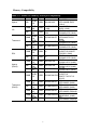
Memory Compatibility Table 1.
Network Feature Comparison Table 1.
Product warranty Advantech warrants to you, the original purchaser, that each of its products will be free from defects in materials and workmanship for two years from the date of purchase. This warranty does not apply to any products which have been repaired or altered by persons other than repair personnel authorized by Advantech, or which have been subject to misuse, abuse, accident or improper installation. Advantech assumes no liability under the terms of this warranty as a consequence of such events.
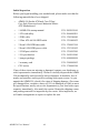
Initial Inspection Before you begin installing your motherboard, please make sure that the following materials have been shipped: • AIMB-556 Socket 478 Intel Core 2 Duo / Core Solo Processor-based Industrial MicroATX Motherboard • 1 AIMB-556 startup manual P/N: 2002055610 • 1 CD with utility P/N: 2066000E11 • 1 FDD cable P/N: 1700340640 • 1 Ultra ATA 66/100 HDD cable P/N: 1701400452 • 2 Serial ATA HDD data cable P/N: 1700003194 • 2 Serial ATA HDD power cable P/N: 1703150102 • 1 COM port
Contents Chapter 1 Hardware Configuration .................................2 1.1 1.2 1.3 Introduction ....................................................................... 2 Features ............................................................................. 3 Specifications .................................................................... 4 1.3.1 1.3.2 1.3.3 1.3.4 1.3.5 1.3.6 1.3.7 1.4 System............................................................................. 4 Memory...................
2.3 2.4 2.5 2.6 2.7 2.8 2.9 2.10 2.11 Floppy Drive Connector (FDD1) .................................... 19 Parallel Port (LPT1) ........................................................ 20 USB Ports (LAN1_USB12, LAN2_USB34, USB56 & USB78)............................................................................ 21 VGA Connector (VGA1) ................................................ 22 Serial Ports (COM1, COM2, COM3 & COM4) ............. 23 PS/2 Keyboard and Mouse Connector (KBMS1) ...........
3.3.2 3.3.3 3.3.4 3.3.5 3.4 PCI/PNP Setup ................................................................ 57 3.4.1 3.4.2 3.4.3 3.4.4 3.4.5 3.4.6 3.4.7 3.4.8 3.5 Figure 3.5:CPU Configuration Setting ......................... 50 IDE Configuration ........................................................ 51 Figure 3.6:IDE Configuration....................................... 51 Super I/O Configuration ............................................... 52 Figure 3.7:Super I/O Configuration......................
5.2 Chapter 6 Onboard Security Setup ................................82 6.1 6.2 6.3 Chapter Windows XP Driver Setup.............................................. 77 Introduction ..................................................................... 82 Windows XP Driver Setup.............................................. 83 Using the OBS Hardware Doctor Utility ........................ 87 7 LAN Configuration ........................................90 7.1 7.2 7.3 7.4 Introduction ........................
Table B.13:Infrared Connector (JIR1)........................ 117 B.14 CPU/System Fan Power Connector (CPUFAN1/ SYSFAN1/SYSFAN2).................................................. 117 Table B.14:Fan Power Connector (CPUFAN1/ SYSFAN1/SYSFAN2)............................ 117 B.15 Power LED and Keyboard Lock (JFP3) ....................... 118 B.16 External Speaker Connector (JFP2) .............................. 119 B.17 Reset Connector (JFP1)................................................. 119 B.
AIMB-556 User Manual xiv
CHAPTER 1 Hardware Configuration 1 Chapter 1
Chapter 1 Hardware Configuration 1.1 Introduction The AIMB-556 is designed with the Intel GME965 and the ICH8M for industrial applications that require both high-performance computing and enhanced power management capabilities. The motherboard supports Intel Core 2 Duo / Core Solo Processors up to 2.6 GHz with 533/800 MHz front side bus and DDR2 400/533/667 MHz memory up to 4 GB. AIMB-556 offers high-performance cost-saving integrated graphics, built on the Intel GME965 chipset.
1.2 Features • PCI Express architecture: Designed with the Intel GME965 and ICH8M PCI Express chipset, the AIMB-556 has single or dual PCIe x1 Gigabit LAN ports, 1 PCIe x16 slot and 1 PCIe x4 slot. • High Performance I/O Capability: Single or dual PCIe x1 Gigabit LAN ports, 2 PCI 32-bit/33 MHz PCI slots, 3 SATA connectors and 8 USB 2.0 ports.
1.3 Specifications 1.3.1 System • CPU: Socket 478 Intel Core 2 Duo / Core Solo up to 2.6 GHz; Intel Core 2 Duo 533/800 MHz FSB. • L2 Cache: CPU has built-in 2 MB or 4 MB CPU and full-speed L2 cache. • BIOS: AMI SPI BIOS (16 Mb SPI) • System Chipset: Intel GME965 with ICH8M • SATA/EIDE hard disk drive interface: Three onboard SATA connectors with data transmission rates of up to 300 MB/s support up to two devices. One onboard IDE connector supports up to two enhanced IDE devices.
1.3.4 Graphics • Controller: Chipset integrated VGA controller • Display memory: Dynamically shared system memory up to 224 MB • CRT: Up to 2048 x 1536 resolution, 400 MHz RAMDAC • LVDS interface: Support up to UXGA (1600 x 1200) • TV-Out: NTSC/PAL.
1.4 Jumpers and Connectors Connectors on the AIMB-556 motherboard link it to external devices such as hard disk drives and a keyboard. In addition, the board has a number of jumpers used to configure your system for your application. The tables below list the function of each of the board jumpers and connectors. Later sections in this chapter give instructions on setting jumpers. Chapter 2 gives instructions for connecting external devices to your motherboard. Table 1.
Table 1.2: Connector/Jumper list Label Function CMOS1 CMOS clear ( Default 1-2 ) JWDT1 Watchdog Reset IDE1 Primary IDE connector (one channel ) FDD1 FDD connector LPT1 Parallel port, Parallel port x 1, supports SPP/EPP/ECP mode LAN1_USB12 LAN1 / USB port 1, 2 LAN2_USB34 LAN2 / USB port 3, 4 VGA1 VGA connector VGA2 TV-Out connector J16 LCD power 3.
Table 1.
1.5 Board Layout: Jumper and Connector Locations CN1 HD1 PCI2 PCI1 LAN2 USB34 PCIEX4 PCIEX16 LAN1 USB12 VGA1 VGA1 KBMS1 AUDIO1 LPT1 CHAFAN2 J16 VGA2 VP1 LVDS1 COM3 COM4 SPI_CS_CN1 Update First SPI: 1-2 CLose Update Second SPI: 2-3 CLose CPU1 PSON1 USB56 CPUFAN1 USB78 CMOS1 SATA2 SATA3 JIR1 ATX2 JWDT1 CN22 JSETCOM2 DIMMB1 DIMMA1 SATA1 JFP1,2,3 JCASE1 IDE1 SYSFAN1 CN2 ATX1 FDD1 Figure 1.
1.6 AIMB-556 Block Diagram 533/800 CRT MHz FSB Intel Socket 478 Core 2 Duo/Core Solo Processor VGA Channel A DDR2 533/667 Channel B DDR2 533/667 Intel GME965 GMCH LVDS 1 ATA 100 port DMA 33/66/100 2 SATA ports 300MB/s 2 GB/s bandwidth PCIe x16 Direct Media Interface PCI Express x16 slot G-LAN1: 82566MM 8 USB Ports USB 2.0/1.1 Audio Codec HD Audio 32bit/33MHz PCI Bus ICH8M SPI BIOS LPC Super IO Winbond W83627HG Figure 1.
1.7 Safety Precautions Warning! Always completely disconnect the power cord from your chassis whenever you work with the hardware. Do not make connections while the power is on. Sensitive electronic components can be damaged by sudden power surges. Only experienced electronics personnel should open the PC chassis. Caution! Always ground yourself to remove any static charge before touching the motherboard. Modern electronic devices are very sensitive to static electric charges.
1.8 Jumper Settings This section provides instructions on how to configure your motherboard by setting the jumpers. It also includes the motherboard’s default settings and your options for each jumper. 1.8.1 How to set jumpers You can configure your motherboard to match the needs of your application by setting the jumpers. A jumper is a metal bridge that closes an electrical circuit.
1.8.3 Watchdog timer output (JWDT1) The AIMB-556 contains a watchdog timer that will reset the CPU or send a signal to IRQ11 in the event the CPU stops processing. This feature means the AIMB-764 will recover from a software failure or an EMI problem. The J2 jumper settings control the outcome of what the computer will do in the event the watchdog timer is tripped. Table 1.
1.8.4 COM2 RS-232/422/485 mode selector (JESTCOM2) Users can use JESTCOM2 to select among RS-232/422/485 modes for COM2. The default setting is RS-232. Figure 1.4: COM2 RS-232/422/485 Jumper setting Table 1.
1.9 System Memory The AIMB-556 has four sockets for 240-pin dual inline memory modules (DIMMs) in two memory channels. All these sockets use 1.8 V unbuffered double data rate synchronous DRAMs (DDR SDRAM). They are available in capacities of 256 MB, 512 MB, 1024 MB and 2 GB. The sockets can be filled in any combination with DIMMs of any size, giving a total memory size between 256 MB and 4 GB. 1.9.1 CPU FSB and memory speed The AIMB-556 can accept DDR2 SDRAM memory chips without parity.
1.12 Processor Installation Warning! Without a fan or heat sink, the CPU will overheat and cause damage to both the CPU and the single board computer. To install a CPU, first turn off your system. The AIMB-556 is designed for Intel Core 2 Duo / Core Solo (socket 478) up to 2.6 GHz. Follow these steps to install the processor: 1. Turn the screw to loosen the processor socket. 2. Align the triangular marking on the processor with the small arrow on the corner of the socket. 3.
CHAPTER 2 Connecting Peripherals 17 Chapter 2
Chapter 2 Connecting Peripherals 2.1 Introduction You can access most of the connectors from the top of the board as it is being installed in the chassis. If you have a number of cards installed, you may need to partially remove the card to make all the connections. 2.
Unlike floppy drives, IDE hard drives can connect in either position on the cable. If you install two drives to a single connector, you will need to set one as the master and the other as the slave. You do this by setting the jumpers on the drives. If you use just one drive on the connector, you should set the drive as the master. See the documentation that came with your drive for more information. Connect the first hard drive to the other end of the cable.
2.
2.5 USB Ports (LAN1_USB12, LAN2_USB34, USB56 & USB78) The AIMB-556 provides up to eight USB (Universal Serial Bus) ports with complete Plug & Play and hot swap support for up to 127 external devices. These USB ports comply with USB Specification Rev. 2.0, support transmission rates up to 480 Mbps and are fuse protected. The USB interface can be disabled in the system BIOS setup.
2.
2.
2.
2.
2.
2.11 Front Panel Connectors (JFP1, JFP2 & JFP3) There are several external switches to monitor and control the AIMB556.
2.11.2 External Speaker (JFP2) JFP2 is a 4-pin connector for an external speaker. The AIMB-556 provides an onboard buzzer as an alternative to an external speaker. To enable the buzzer, set pins 5 and 7 as closed. 2.11.3 Reset Connector (JFP1) Many computer cases offer the convenience of a reset button. Connect the wire from the reset button. 2.11.4 HDD LED Connector (JFP2) You can connect an LED to connector JFP2 to indicate when the HDD is active. 2.11.
2.
2.
2.
2.
2.
2.
2.18 Front Panel LAN Indicator Connector (LANLED1) Table 2.
2.
2.
2.
2.
2.23 Auxiliary 4-pin power connector (ATX1) To ensure enough power is supplied to the motherboard, one auxiliary 4pin power connector is available on the AIMB-556. ATX1 must be used to provide sufficient 12 V power to ensure stable operation of the system.
2.
2.
2.
AIMB-556 User Manual 44
CHAPTER 3 AMI BIOS Setup 45 Chapter 3
Chapter 3 AMI BIOS Setup AMIBIOS has been integrated into many motherboards for over a decade. In the past, people often referred to the AMIBIOS setup menu as BIOS, BIOS setup or CMOS setup. With the AMIBIOS Setup program, you can modify BIOS settings and control the special features of your computer. The Setup program uses a number of menus for making changes and turning the special features on or off. This chapter describes the basic navigation of the AIMB-556 setup screens. Figure 3.
3.1 Entering Setup Turn on the computer and check for the “patch” code. If there is a number assigned to the patch code, it means that the BIOS supports your CPU. If there is no number assigned to the patch code, please contact an Advantech application engineer to obtain an up-to-date patch code file. This will ensure that your CPU’s system status is valid. After ensuring that you have a number assigned to the patch code, press and you will immediately be allowed to enter Setup. Figure 3.
3.2 Main Setup When you first enter the BIOS Setup Utility, you will enter the Main setup screen. You can always return to the Main setup screen by selecting the Main tab. There are two Main Setup options. They are described in this section. The Main BIOS Setup screen is shown below. Figure 3.3: Main setup screen The Main BIOS setup screen has two main frames. The left frame displays all the options that can be configured. Grayed-out options cannot be configured; options in blue can be.
3.3 Advanced BIOS Features Setup Select the Advanced tab from the AIMB-556 setup screen to enter the Advanced BIOS Setup screen. You can select any of the items in the left frame of the screen, such as CPU Configuration, to go to the sub menu for that item. You can display an Advanced BIOS Setup option by highlighting it using the keys. All Advanced BIOS Setup options are described in this section. The Advanced BIOS Setup screens is shown below. The sub menus are described on the following pages.
3.3.1 CPU Configuration Figure 3.5: CPU Configuration Setting Max CPUID Value Limit This is disabled for Windows XP. Vanderpool Technology This feature is used to enable or disable the Intel Virtualization Technology (IVT) extension, which also goes by the development code name of Vanderpool. It allows multiple operating systems to run simultaneously on the same system. It does this by creating virtual machines, each running its own x86 operating system.
Inter(R) speedstep(tm) tech Intel SpeedStep Technology centralizes the control mechanism in the processor, eliminating the need for coordination with the chipset during the frequency/voltage configuration. This option is used to enable/disable the GV3 bit. 3.3.2 IDE Configuration Figure 3.6: IDE Configuration ATA/IDE Configuration This can be configured as Disabled, Compatible or Enhanced. Configure SATA as This can be configured as IDE, RAID or AHCI. RAID will be activated by the ICH8M-E only.
Primary IDE Slave While entering setup, the BIOS automatically detects the presence of IDE devices. This displays the status of IDE device auto-detection. Secondary/Third/Fourth IDE Master While entering setup, the BIOS automatically detects the presence of IDE devices. This displays the status of IDE device auto-detection. Secondary/Third/Fourth IDE Slave While entering setup, the BIOS automatically detects the presence of IDE devices. This displays the status of IDE device auto-detection.
OnBoard Floppy Controller This option allows the BIOS to Enable or Disable the floppy controller. Floppy A Select the type of floppy drive connected to the system. We suggest you disable the floppy while installing Windows Vista without a floppy drive. Floppy B Select the type of floppy drive connected to the system. Serial Port1 Address This option configures serial port 1 base addresses. Serial Port2 Address This option configures serial port 2 base addresses.
3.3.4 Hardware health function Figure 3.8: Hardware health configuration. Hardware health function Enable/Disable the onboard hardware monitor controller. If this option is enabled, the BIOS and OBS utility can get the system board’s health information from hardware monitor controller. Chassis Intrusion Enable/Disable the Chassis Intrusion monitoring function. When the case is opened, the buzzer beeps.
3.3.5 APM Configuration Figure 3.9: APM Configuration Power Management/APM Enable or disable APM. Video Power Down Mode Set the Video Power Down mode to the Suspend or Standby mode. Hard Disk Power Down Mode Set Power Down Hard Disk mode to Suspend or Standby mode. Suspend Time Out Enter Suspend after the specified time. Throttle Slow Clock Ratio Select the duty cycle in throttle mode. Keyboard & PS/2 Mouse When you set this to Monitor, you can monitor the PS/2 keyboard and mouse ports.
Power Button Mode Power on, off or enter suspend mode when the power button is pressed. The following options are also available. • Resume On Ring: Disable/Enable RI wake event. • Resume On LAN: Disable/Enable LAN PME wake event. • Resume On RTC Alarm: Disable/Enable RTC wake event. Figure 3.10: Configure Remote Access type and parameters Remote Access You can disable or enable the BIOS remote access feature here. This function is used to redirect the console from the serial port.
3.4 PCI/PNP Setup Select the PCI/PnP tab from the AIMB-556 setup screen to enter the Plug and Play BIOS Setup screen. You can display a Plug and Play BIOS Setup option by highlighting it using the keys. All Plug and Play BIOS Setup options are described in this section. The Plug and Play BIOS Setup screen is shown below. Figure 3.
Figure 3.12: PCI/PNP Setup (bottom) 3.4.1 Clear NVRAM Set this value to force the BIOS to clear the Non-Volatile Random Access Memory (NVRAM). The Optimal and Fail-Safe default setting is No. 3.4.2 Plug and Play O/S Set this value to allow the system to modify the settings for Plug and Play operating system support. The Optimal and Fail-Safe default setting is No. 3.4.3 PCI Latency Timer Use this to adjust the PCI Latency Timer. This option sets the latency of all PCI devices on the PCI bus.
3.4.5 Palette Snooping Set this value to allow the system to modify the Palette Snooping settings. The Optimal and Fail-Safe default setting is Disabled. 3.4.6 PCI IDE BusMaster Set this value to allow or prevent the use of PCI IDE Busmastering. The Optimal and Fail-Safe default setting is Disabled. 3.4.7 Off Board PCI/ISA IDE Card Set this value to allow an add-on PCI/ISA IDE card to be selected. The Optimal and Fail-Safe default setting is Auto. 3.4.
3.5 Boot Setup Utility Figure 3.
Figure 3.14: Boot Setting Configuration The following options are available: • Quick Boot: Allows the BIOS to skip certain tests while booting. This will decrease the time needed to boot the system. • Quiet Boot: If this option is set to Disabled, the BIOS displays normal POST messages. If Enabled, an OEM Logo is shown instead of POST messages. • Bootup Num-Lock: Select the Power-on state for Numlock. • Wait For ‘F1’ If Error: Wait for the F1 key to be pressed if an error occurs.
3.6 Security Setup Figure 3.15: Password Configuration Select Security Setup from the AIMB-556 Setup main BIOS setup menu. All Security Setup options, such as password protection and virus protection are described in this section. To access the sub menu for the following items, select the item and press : • Change Supervisor Password • Boot sector Virus protection: The boot sector virus protection will warn if any program tries to write to the boot sector.
3.7 Advanced Chipset Settings Figure 3.
Figure 3.17: North Bridge Configuration The following options are available: • Boots Graphic Adapter Priority: Select which graphics controller to use as the primary boot device. • Internal Graphics Mode Select: Select the amount of system memory used by the Internal graphics device. • PEG Port: Auto or Disabled. • PEG Force x1: Enabled or Disabled.
Figure 3.18: Video function configuration DVMT model select Displays the active system memory mode. DVMT / FIXED Memory Specify the amount of DVMT / FIXED system memory to allocate for video memory. Boot display device Select boot display device at post stage.
Figure 3.19: South Bridge Configuration The following options are available: • USB Functions: Disabled, 2 USB Ports, 4 USB Ports, 6 USB Ports or 8 USB Ports. • USB 2.0 Controller: Enables or disables the USB 2.0 controller. • GbE Controller: Enables or disables the GbE controller. • GbE LAN boot: Enables or disables GbE LAN boot. • LAN2 Controller: Enables or disables the LAN2 controller. • HDA Controller: Enables or disables the HDA controller. • SMBUS Controller: Enables or disables the SMBUS controller.
3.8 Exit Option Figure 3.20: Exit Option 3.8.1 Save Changes and Exit When you have completed system configuration, select this option to save your changes, exit BIOS setup and reboot the computer so the new system configuration parameters can take effect. 1. Select Exit Saving Changes from the Exit menu and press . The following message appears: Save Configuration Changes and Exit Now? [Ok] [Cancel] 2. Select Ok or cancel.
3.8.2 Discard Changes and Exit Select this option to quit Setup without making any permanent changes to the system configuration. 1. Select Exit Discarding Changes from the Exit menu and press . The following message appears: Discard Changes and Exit Setup Now? [Ok] [Cancel] 2. Select Ok to discard changes and exit. Discard Changes 3. Select Discard Changes from the Exit menu and press . 3.8.
CHAPTER 4 Chipset Software Installation Utility 69 Chapter 4
Chapter 4 Chipset Software Install Utility 4.1 Before you begin To facilitate the installation of the enhanced display drivers and utility software, read the instructions in this chapter carefully. The drivers for the AIMB-556 are located on the software installation CD. The auto-run function of the driver CD will guide and link you to the utilities and drivers under a Windows system. The Intel Chipset Software Installation Utility is not required on systems running Windows NT 4.0.
4.2 Introduction The Intel Chipset Software Installation (CSI) utility installs the Windows INF files that outline to the operating system how the chipset components will be configured. This is needed for the proper functioning of the following features: • Core PCI PnP services • IDE Ultra ATA 100/66/33 and Serial ATA interface support • USB 1.1/2.0 support (USB 2.
4.3 Windows XP Driver Setup 1. Insert the driver CD into your system’s CD-ROM drive. In a few seconds, the software installation main menu appears. Move the mouse cursor over the “Install” button under the “INF Driver” heading. A message pops up telling you to install the INF Drvier before other device drivers, as shown in the following figure. Click on this button. To take Windows XP as example.
2. Click “Next” when you see the following message. 3. Click “Next” when you see the following message.
4. When the following message appears, click “Finish” to complete the installation and restart Windows.
CHAPTER 5 VGA Setup 75 Chapter 5
Chapter 5 VGA Setup 5.1 Introduction The Intel GME965 integrated graphics controller provides an analog display port, an LVDS interface and a TV-out interface. You need to install the VGA driver to enable the function. The Intel GME965 integrated graphics controller includes the following features.
5.2 Windows XP Driver Setup Note: Before installing this driver, make sure the INF Driver has been installed on your system. See Chapter 4 for information on installing the INF Driver. Insert the driver CD into your system's CD-ROM drive. In a few seconds, the software installation main menu appears, as shown in the following figure. The following installation procedure is for Windows XP.
1. Click “Next” to continue the installation. 2. You will see a welcome window. Click “Yes” to continue the installation.
3. Click “Finish” to complete the installation and restart the computer now or later. Notice: For the first bootup after installation of a VGA driver for Windows Vista 32- or 64-bit OS, there may be around 30 to 60 seconds with black screen while the VGA output is detected. Subsequent bootups do not experience this delay.
CHAPTER 6 Onboard Security Setup 81 Chapter 6
Chapter 6 Onboard Security Setup 6.1 Introduction The AIMB-556’s hardware monitor is based on the Winbond W83627HG chip. Onboard security (OBS) functions monitor key hardware to help you maintain system stability and durability. The AIMB-556 can monitor five sets of positive system voltages, two sets of system negative voltages, CPU fan speed and CPU temperature. The positive system voltage sets that can be monitored include: • CPU core voltage: 1.3 ~ 3.
6.2 Windows XP Driver Setup 1. Insert the driver CD into your system’s CD-ROM drive. In a few seconds, the software installation main menu appears, as shown in the following figure. Click on the “Install” button under the “OBS Drivers” heading.
2. Click “Next” when you see the following message. 3. Click “Next” when you see the following message.
4. Click “Next” when you see the following message.
5. Click “Finish” when you see the following message. 6. Click “Finish” when you see the following message.
6.3 Using the OBS Hardware Doctor Utility After completing the setup, all the OBS functions are permanently enabled. When a monitored reading exceeds safe limits, a warning message will be displayed and an error beep will sound to attract your attention. OBS Hardware Doctor will show an icon on the right side of the bottom window bar. This icon is the “Terminate and Stay Resident” (TSR) icon.
AIMB-556 User Manual 88
CHAPTER 7 LAN Configuration 89 Chapter 7
Chapter 7 LAN Configuration 7.1 Introduction The AIMB-556 has a single/dual Gigabit Ethernet LAN with a dedicated PCI Express x1 connection (Intel 82573) that offers bandwidth of up to 500 MB/sec. This eliminates network data flow bottlenecks for Gigabit Ethernet. 7.2 Features • 10/100/100Base-T Ethernet Controller • 10/100/1000Base-T triple-speed MAC • High-speed RISC core with 24-KB cache • On-chip voltage regulation • Wake-on-LAN (WOL) support • PCI Express x1 host interface 7.
7.4 Win XP Driver Setup 1. Insert the driver CD into your system’s CD-ROM drive. In a few seconds, the software installation main menu appears, as shown in the following figure. Under LAN drivers, click the button that is labelled with your operating system.
2. Select “I accept the terms in the license agreement” and click “Next” to continue. 3. Click “Next” to continue.
4. Click “Install Software” to start the installation procedure. 5. The driver will be installed automatically and the LAN function will be enabled after the installation.
AIMB-556 User Manual 94
Appendix A Programming the Watchdog Timer 95 Appendix A
Appendix A Programming the Watchdog Timer A.1 Introduction The AIMB-556’s watchdog timer can be used to monitor system software operation and take corrective action if the software fails to function within the programmed period. This section describes the operation of the watchdog timer and how to program it. A.1.1 Watchdog timer overview The watchdog timer is built in to the W83627HG super I/O controller.
Unlock W83627HG Select register of watchdog timer Enable the function of the watchdog timer Use the function of the watchdog timer Lock W83627HG 97 Appendix A
Table A.1: Watchdog timer registers Address of register (2E) Attribute Read/ Write Value (2F)& description 87 (hex) ----- Write this address to I/O address port 2E (hex) twice to unlock the W83627HG 07 (hex) write Write 08 (hex) to select register of watchdog timer. 30 (hex) write Write 01 (hex) to enable the function of the watchdog timer. Disabled is set as default. F5 (hex) write Set seconds or minutes as units for the timer. Write 0 to bit 3: set second as counting unit. [default].
A.1.3 Example Program 1. Enable watchdog timer and set 10 sec.
Inc dx Mov al,10 Out dx,al ;----------------------------------------------------------Dec dx ; lock W83627HG Mov al,0aah Out dx,al 2.
In al,dx Or al,08h Out dx,al ;----------------------------------------------------------Dec dx ; Set timeout interval as 5 minutes and start counting Mov al,0f6h Out dx,al Inc dx Mov al,5 Out dx,al ;----------------------------------------------------------Dec dx ; lock W83627HG Mov al,0aah Out dx,al 3.
Mov al,01h Out dx,al ;----------------------------------------------------------Dec dx ; Enable watchdog timer to be reset by mouse Mov al,0f7h Out dx,al Inc dx In al,dx Or al,80h Out dx,al ;----------------------------------------------------------Dec dx ; lock W83627HG Mov al,0aah Out dx,al 4.
Mov al,01h Out dx,al ;----------------------------------------------------------Dec dx ; Enable watchdog timer to be strobed reset by keyboard Mov al,0f7h Out dx,al Inc dx In al,dx Or al,40h Out dx,al ;----------------------------------------------------------Dec dx ; lock W83627HG Mov al,0aah Out dx,al 5.
Mov al,01h Out dx,al ;----------------------------------------------------------Dec dx ; Generate a time-out signal Mov al,0f7h Out dx,al Inc dx In al,dx ;Write 1 to bit 5 of F7 register Or al,20h Out dx,al ;----------------------------------------------------------Dec dx ; lock W83627HG Mov al,0aah Out dx,al AIMB-556 User Manual 104
Appendix B I/O Pin Assignments
Appendix B Pin Assignments B.1 IDE Hard Drive Connector (IDE1) Table B.
B.2 Floppy Drive Connector (FDD1) 33 31 3 1 34 32 4 2 Table B.
B.3 Parallel Port (LPT1) Table B.
B.4 USB Header (USB56/USB78) Table B.
B.5 VGA Connector (VGA1) 5 1 10 6 15 11 Table B.5: VGA Connector (VGA1) Pin Signal Pin Signal 1 RED 9 VCC 2 GREEN 10 GND 3 BLUE 11 N/C 4 N/C 12 SDT 5 GND 13 H-SYNC 6 GND 14 V-SYNC 7 GND 15 SCK B.6 TV-out connector (VGA2) Table B.
B.7 RS-232 Interface (COM1) 5 4 3 2 1 9 8 7 6 COM1 Table B.
B.8 RS-232/422/485 Interface (COM2) 2 4 6 8 1 3 5 7 9 COM2 Table B.
B.9 RS-232 Interface (COM3/COM4) 5 4 3 2 1 9 8 7 6 5 4 3 2 1 COM3 9 8 7 6 COM4 Table B.
B.10 LVDS Connector (LVDS1) Table B.
B.11 LCD Inverter Power connector (VP1) Table B.11: VP 1 Pin Signal 1 +12V 2 GND 3 L_BKLTEN 4 VBR 5 +5V B.12 PS/2 Keyboard and Mouse Connector (KBMS1) Table B.
Table B.
B.13 Infrared (IR) connector (JIR1) Table B.13: Infrared Connector (JIR1) Pin Signal 1 VCC 2 N/C 3 IRRX 4 GND 5 IRTX B.14 CPU/System Fan Power Connector (CPUFAN1/ SYSFAN1/SYSFAN2) Table B.
B.15 Power LED and Keyboard Lock (JFP3) Table B.
B.16 External Speaker Connector (JFP2) Table B.16: External Speaker LED connector (JFP2) Pin Function 1 Speaker out 2 HDD(LED+) 3 NC 4 HDD(LED-) 5 Buzzer 6 NC 7 Buzzer 8 NC B.17 Reset Connector (JFP1) 3 4 Table B.
B.18 ATX Soft Power Switch (JFP1) 1 Table B.18: ATX Soft Power Switch (JFP3) Pin Signal 1 5VSB 2 PWR-BTN B.19 H/W Monitor Alarm (CN22) Table B.
B.20 USB/LAN ports (LAN1_USB12 and LAN2_USB34) Table B.20: USB Port Pin Signal Pin Signal 1 VCC 3 Data0+ 2 Data0- 4 GND Table B.21: Ethernet 10/100Base-T RJ-45 port Pin Signal Pin Signal 1 XMT+ 5 N/C 2 XMT- 6 RCV- 3 RCV+ 7 N/C 4 N/C 8 N/C B.
B.22 Audio Input from CD-ROM (CD IN; CN1) Table B.
B.
B.24 Case Open Connector (JCASE1) 1 Table B.24: Case Open Connector (JCASE) Pin Signal 1 CASEOP 2 GND B.25 Front Panel LAN LED Connector (LANLED1) 1 2 3 4 5 6 7 8 9 10 Table B.
B.26 System I/O Ports Table B.26: System I/O ports Addr.
B.27 DMA Channel Assignments Table B.
B.28 Interrupt Assignments Table B.
AIMB-556 User Manual 128