User Manual ACP-2010MB 2U-High Rackmount Chassis for ATX / MicroATX Motherboard
Copyright The documentation and the software included with this product are copyrighted 2008 by Advantech Co., Ltd. All rights are reserved. Advantech Co., Ltd. reserves the right to make improvements in the products described in this manual at any time without notice. No part of this manual may be reproduced, copied, translated or transmitted in any form or by any means without the prior written permission of Advantech Co., Ltd. Information provided in this manual is intended to be accurate and reliable.
Safety Instructions 1. 2. 3. 4. 5. 6. 7. 8. 9. 10. 11. 12. 13. 14. 15. 16. 17. Read these safety instructions carefully. Keep this user manual for later reference. Disconnect this equipment from AC outlet before cleaning. Do not use liquid or spray detergents for cleaning. For pluggable equipment, the power outlet shall be installed near the equipment and shall be easily accessible. Keep this equipment away from humidity. Put this equipment on a reliable surface during installation.
18. This device complies with Part 15 of the FCC rules. Operation is subject to the following two conditions: (1) this device may not cause harmful interference, and (2) this device must accept any interference received, including interference that may cause undesired operation. 19. CAUTION: Always completely disconnect the power cord from your chassis whenever you work with the hardware. Do not make connections while the power is on. Sensitive electronic components can be damaged by sudden power surges.
Product Warranty (2 years) Advantech warrants to you, the original purchaser, that each of its products will be free from defects in materials and workmanship for two years from the date of purchase. This warranty does not apply to any products which have been repaired or altered by persons other than repair personnel authorized by Advantech, or which have been subject to misuse, abuse, accident or improper installation.
Initial Inspection When you open the carton, please make sure that the following materials have been shipped: ! ACP-2010MB Chassis ! User Manual ! Warranty Card ! Accessory box with a package of screws (for fastening the motherboard, disk drives, ears and handles, etc.), a pair of keys, a plastic post, a pair of ears and handles. If any of these items are missing or damaged, contact your distributor or sales representative immediately.
Contents Chapter 1 General Information ............................1 1.1 1.2 1.3 Introduction ............................................................................................... 2 Specifications ............................................................................................ 2 Power Supply Options............................................................................... 3 Table 1.1: Power supply options .................................................
4.3 Appendix A Table 4.1: CN1, Auxiliary external power connector, standard mini 4-Pin power connector....................... 25 Table 4.2: CN4, Thermal sensor (LM75) connector .................. 25 Table 4.3: CN13, Voltage detect. input connector..................... 25 Table 4.4: CN16, Power good input connector ......................... 25 Table 4.5: CN17, Alarm reset connector ................................... 25 Table 4.6: CN18, Output connector to LED board .................... 26 Table 4.
Chapter 1 1 General Information This chapter provides general information about the ACP2010MB.
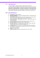
1.1 Introduction The ACP-2010MB is a 2U-high rackmount industrial computer chassis. It meets a variety of application needs for filing, printing, e-mails and web serving. This powerful computing platform is suitable for mission-critical computer telephony applications, industrial automation, and factory management. A wide range of standard computing peripherals can be integrated with the chassis to meet different application needs for operation under harsh conditions 24 hours a day, 7 days a week. 1.
Table 1.1: Power supply options 1757000007G 1757000105G Watts 300 W (ATX, PFC) (single) 400 W (ATX, PFC) (single) Input rating 100 ~ 240 Vac (Full range) 100 ~ 240 Vac (Full range) Output voltage +5 V @ 35 A, +3.3 V @ 20 A, +12 V @ 16 A, -5 V @ 0.5 A, -12 V @ 1 A, +5 Vsb @ 2 A +5 V @ 25 A, +3.3 V @ 20 A, +12 V @ 28 A, -5 V @ 0.5 A, -12 V @ 0.5 A, +5 Vsb @ 2 A Minimum load +5 V @ 3 A, +3.3 V @ 1 A, +12 V @ 2 A, -5 V @ 0.05 A, -12 V @ 0.05 A, +5 Vsb @ 0.1 A +5 V @ 3 A, +3.
1.5 Dimension Diagram Unit: mm [inch] Figure 1.
Chapter 2 2 System Setup This chapter introduces the installation process.
The following procedures instruct users to install a motherboard, add-on cards, and disk drives into the ACP-2010MB. Refer to Appendix A, the Exploded Diagram and the Parts List for more detailed information about parts for the ACP-2010MB. Note! Use caution when installing or operating the components with the chassis open. Be sure to turn off the power, unplug the power cord and ground yourself by touching the metal chassis before you handle any components inside the machine. 2.
The ACP-2010MB can support an ATX / MicroATX motherboard with up to three addon cards via the expanded riser card, or seven low profile add-on cards via the optional special rear I/O bracket. To install the motherboard, please proceed as follows: Note! Remove the card holder by loosening the two screws. A yellow label is located inside of the chassis bottom. (see Figure 2.2) The label shows the plastic post locations for attaching specific Advantech motherboards.
Figure 2.3 Fasten the plastic post Figure 2.
Figure 2.5 Installing a riser card 9 ACP-2010MB User Manual System Setup The ACP-2010MB supports up to three add-on cards via the riser card. To install the riser card and one or more add-on cards, please proceed as follows: 1. Fasten the riser card to the riser card holder with the four screws. Then insert this unit into the slot on the motherboard. (See Figure 2.5.) 2. Remove the corresponding I/O bracket attached to the rear plate of the chassis.
Figure 2.6 Installing an add-on card Note! These riser cards are specially designed to support Advantech AIMB7XX and AIMB-5XX series motherboards. There may be compatibility issues if used with other vendor's motherboards. If you have the ACP-2010MB with the low-profile rear I/O bracket, then simply install the low-profile add-on card to the selected PCI/PCIe slot on the motherboard, and fasten the card securely.
The ACP-2010MB supports one 5.25" optical disk drive and three 3.5" disk drives (one FDD and two internal HDDs). Figure 2.7 Installing the internal HDD 11 ACP-2010MB User Manual System Setup To install the 3.5” internal HDD, 5.25" optical disk drive and the 3.5" FDD, please follow these steps for installation: 1. To install the 3.5" internal HDD, simply release the four screws on top of the disk drive bracket. 2.
4. 5. 6. 7. To install the optical disk drive and 3.5" FDD, undo the screws on the 5.25" disk drive bracket. Undo the screws on each side of the 5.25" disk drive bracket to remove the front covers. Slide the optical disk drive and the FDD into the bracket and fasten it on both sides with the eight screws provided (see Figure 2.9). Return the 5.25" disk drive bracket with the disk drives in the original position and reattach it inside the chassis with the original screws.
There are a pair of ears and handles in the accessory box, which may be added to the front end of the chassis for easy handling. To install the handles onto the chassis, refer to Figure 2.9 and attach the ears to the chassis, and the handles to the ears on the front-right and front-left edges with the screws provided. Chapter 2 2.5 Attaching the Ears and Handles System Setup Figure 2.
ACP-2010MB User Manual 14
Chapter 3 3 Operation This chapter introduces the system operation information.
3.1 The Front Panel The front panel features a lockable door and four LED indicators. It provides front accessible, dual USB ports and a PS/2 connector. The front door can be closed with or without a key using the user-friendly rotary lock. Behind the opening door is a Momentary Power switch, a System Reset button, and an Alarm Reset button. Specific functions are described below: Figure 3.1 Front panel with door closed Figure 3.2 Front panel with door open 3.1.
Four LEDs are placed on the left side of the front panel to indicate system health and activity. Refer to Table 3.1 for an LED definition summary. Table 3.1: LED indicator functions LED Green Red System power Normal Abnormal Hard disk drive activity Data access No light Temperature in the chassis Normal Abnormal Cooling fan status Normal Abnormal When the system power is on, the power LED is Green. If the power LED is RED, it indicates a redundant power supply module failure.
3.2 The Rear Panel The rear panel comes with 3-slot I/O brackets, two reserved 9-pin D-SUB openings and a motherboard I/O opening. (see Figure 3.3) Figure 3.3 Rear panel with standard I/O brackets There is an optional rear I/O bracket for the low profile add-on cards (see Figure 3.4). Figure 3.4 Rear panel with low profile I/O brackets There is a ground screw with a washer located on the lower right of the rear panel. This will protect the system in case of electrical leakage.
There are two easily maintained system cooling fans in the chassis. The fans provide the system with ample cooling by blowing air toward the rear. To replace the fan, proceed as follows: 5. 6. 7. Remove the top cover. Unplug the power connectors from the fans. Loosen the two screws on the fan bracket and gently pull it out. Loosen four screws on the fan in the bracket. Remove the broken fan and replace it with a working one. Fix the working fan onto the bracket with the four screws (see Figure 3.5).
3.4 Cleaning the Filters The filter functions to block dust or particles from the work environment and greatly helps to extend the longevity of the system. It is recommended to check, clean and replace the filters periodically. Two reusable, washable filters are located behind the front door and in front of the system fans. To remove and clean the filter, proceed as follows: 1. Open the front door. 2. To remove the door filter, simply push the hook to pull it out. 3.
The ACP-2010MB supports either a 300 W or a 400 W 2-U-high power supply. To replace the power supply, proceed as follows: 1. 2. 3. 5. 6. 7. Figure 3.7 Replacing the power supply 21 ACP-2010MB User Manual Operation 4. Unplug the power cord from the power supply. Remove the top cover. Unplug the 20-pin (or 24-pin) ATX power connector and 4-pin +12 V power connector from the motherboard, as well as the power connectors from all disk drives.
ACP-2010MB User Manual 22
Chapter 4 4 Alarm Board This chapter introduces the alarm board and thermal sensor specifications. Sections include: ! Alarm board layout ! Alarm board specifications ! Thermal sensor ! Sensor I.D.
The alarm board is located under the 3.5" disk drive bay. The alarm board provides system detection functions that monitor the entire status of the computer system, including: thermal conditions, fans, power supply and HDD operation. Any problems with the system are reported through audible alarms and LED indicators. The alarm board sounds an audible alarm whenever: 1. Any power supply module of the redundant power supply fails; 2. One of the system cooling fans fails; 3.
! ! 4.2.1 Connectors & Pin Definition Table 4.1: CN1, Auxiliary external power connector, standard mini 4-Pin power connector Pin 1 +12 V Pin 3 GND Pin 2 GND Pin 4 +5 V Table 4.2: CN4, Thermal sensor (LM75) connector Pin 1 +5 V Pin 3 T_SDAT Pin 2 T_SCLK Pin 4 GND Table 4.3: CN13, Voltage detect. input connector Pin 1 +5 Vsb Pin 5 +5 V Pin 2 GND Pin 6 +3.3 V Pin 3 GND Pin 7 -12 V Pin 4 -5 V Pin 8 +12 V Table 4.
Table 4.6: CN18, Output connector to LED board Pin 1 GND Pin 9 Temperature Good Pin 2 +5 V signal Pin 10 Temperature Fail Pin 3 +12 V signal Pin 11 FAN Good Pin 4 -5 V signal Pin 12 FAN Fail Pin 5 -12 V signal Pin 13 N/A Pin 6 HDD_1 Pin 14 +3.3 V signal Pin 7 Power Good Pin 15 +5 Vsb signal Pin 8 Power Fail Pin 2 N/A Table 4.7: CN26, HDD LED connector Pin 1 HLED_ACT Table 4.8: FAN1~FAN7, Fan connectors Pin 1 GND Pin 2 +12 V Pin3 FAN_DEC Pin 2 +5 V Table 4.
The alarm board is designed to connect with up to 7 fans. Users can set the fan number by adjusting the switch, SW1, on the alarm board. Table 4.
4.3 Thermal Sensor The ACP-2010MB is configured with a thermal sensor on the backside of the chassis (see Figure 4.2). Thermal sensor Figure 4.2 Thermal sensor location Refer to Figure 4.3 for a diagram of the thermal sensor module layout. Figure 4.3 Thermal sensor module The default sensor I.D. number is 1. Users can refer to Table 4.13 to set the sensor I.D. number by adjusting the switch, SW1, on the sensor module.
Pin 1 +5 V Pin 3 T_SDAT Pin 2 T_SCLK Pin 4 GND Chapter 4 Table 4.12: CN1 & CN2, Temperature sensor connector Table 4.13: SW1, Thermal sensor I.D. setting SW 1-1 SW 1-2 SW 1-3 SW 1-4 1 (default) OFF OFF OFF ON 2 OFF OFF ON ON 3 OFF ON OFF ON 4 OFF ON ON ON 5 ON OFF OFF ON 6 ON OFF ON ON 7 ON ON OFF ON 8 ON ON ON ON 29 ACP-2010MB User Manual Alarm Board Sensor I.D. No.
ACP-2010MB User Manual 30
Appendix A A Exploded Diagram and Parts List
Figure A.1 Exploded Diagram Table A.1: Parts List 1 Key Set 13 Rack Mounting 25 Thermal Board 2 Front Panel 14 Chassis 26 Rear Plate 3 Transparent Sheet 15 Wire Saddle 27 Top Cover 4 Air Filter 16 System Fan 28 Motherboard Plastic Post 5 LED Holder 17 Fan Bracket 29 Power Bracket 6 Front Panel 18 Guide Rail Bracket 30 Power Supply 7 Cable 19 Add-on Card Guide Rail 31 3.5" FDD Cover 8 ATX Cable 20 Alarm Board 32 5.
Appendix B B Motherboard & Riser Card Options
B.1 Motherboard Options The ACP-2010MB supports a variety of Advantech ATX / MicroATX motherboards described below. Contact a local sales representative for more detailed information. Table B.
The riser card is specially designed to support Advantech AIMB series of motherboards. Users can contact a local sales representative for detailed information. Table B.
www.advantech.com Please verify specifications before quoting. This guide is intended for reference purposes only. All product specifications are subject to change without notice. No part of this publication may be reproduced in any form or by any means, electronic, photocopying, recording or otherwise, without prior written permission of the publisher. All brand and product names are trademarks or registered trademarks of their respective companies. © Advantech Co., Ltd.