User Manual AIMB-582 Intel® Xeon® E3/Core™ i7/i5/i3 LGA1155 MicroATX with CRT/ DVI/eDP/LVDS/DP, 6 COM, Dual LAN, DDR3, PCIe x 16 and SATAIII
Copyright The documentation and the software included with this product are copyrighted 2012 by Advantech Co., Ltd. All rights are reserved. Advantech Co., Ltd. reserves the right to make improvements in the products described in this manual at any time without notice. No part of this manual may be reproduced, copied, translated or transmitted in any form or by any means without the prior written permission of Advantech Co., Ltd. Information provided in this manual is intended to be accurate and reliable.
A Message to the Customer Advantech Customer Services Each and every Advantech product is built to the most exacting specifications to ensure reliable performance in the harsh and demanding conditions typical of industrial environments. Whether your new Advantech equipment is destined for the laboratory or the factory floor, you can be assured that your product will provide the reliability and ease of operation for which the name Advantech has come to be known. Your satisfaction is our primary concern.
Declaration of Conformity FCC Class B This device complies with the requirements in part 15 of the FCC rules: Operation is subject to the following two conditions: This device may not cause harmful interference This device must accept any interference received, including interference that may cause undesired operation. This equipment has been tested and found to comply with the limits for a Class B digital device, pursuant to Part 15 of the FCC Rules.
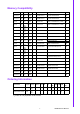
Memory Compatibility Size Speed Type ECC Vendor PN Memory Result Transcend 1GB DDR3 1066 DDR3 N TS128MLK64V1U SEC K4B1G0846G-BCH9 pass Transcend 2GB DDR3 1066 DDR3 N TS256MLK64V1U SEC K4B1G0846G-BCH9 pass Apacer 1GB DDR3 1066 DDR3 N 78.01GC3.420 ELPIDA J1108BDBG-DJ-F (128x8) pass Apacer 2GB DDR3 1066 DDR3 N 78.A1GC3.421 ELPIDA J1108BDBG-DJ-F (128x8) pass Apacer 4GB DDR3 1066 DDR3 N 78.B1GDJ.
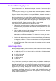
Product Warranty (2 years) Advantech warrants to you, the original purchaser, that each of its products will be free from defects in materials and workmanship for two years from the date of purchase. This warranty does not apply to any products which have been repaired or altered by persons other than repair personnel authorized by Advantech, or which have been subject to misuse, abuse, accident or improper installation.
Contents Chapter 1 General Information ............................1 1.1 1.2 1.3 1.9 1.10 1.11 1.12 1.13 Introduction ............................................................................................... 2 Features .................................................................................................... 2 Specifications ............................................................................................ 2 1.3.1 System ........................................................
2.11 2.12 2.13 2.14 2.15 2.16 2.17 2.18 2.19 2.20 2.21 2.22 2.23 and Mouse Connector (KBMS2) ............................................................. 19 CPU Fan Connector (CPU_FAN1) ......................................................... 20 System FAN Connector (SYSFAN1/2/3/4) ............................................. 20 Front Panel Connectors (JFP1/JFP2/JFP3) ........................................... 21 2.10.1 ATX soft power switch ((JFP1/PWR_SW))................................. 21 2.10.
Chapter 7 LAN Configuration.............................81 7.1 7.2 7.3 7.4 Introduction ............................................................................................. 82 Features .................................................................................................. 82 Installation ............................................................................................... 82 Windows® 7/XP Driver Setup (Intel 82579LM/82583V)..........................
B.21 B.22 B.23 B.24 B.25 B.26 AIMB-582 User Manual ATX 12 V Connector (ATX12V1) .......................................................... 104 Table B.21:ATX 12 V Connector (ATX12V1)............................ 104 JTAG ( Joint Test Action Group Connector) ......................................... 104 Table B.22:Joint Test Action Group (JTAG) ............................. 104 JUSBPWR1-4 (USB Power Selection Connector)................................ 104 Table B.
Chapter 1 1 General Information
1.1 Introduction AIMB-582 is designed with the Intel Q77/C216 for industrial applications that require both performance computing and enhanced power management capabilities. The motherboard supports Intel Core i7 3770 3.4GHz/ Core i5 3550S 3.0 GHz/ Core i3 3220 3.3 GHz/Pentium G850 2.9 GHz/Celeron G540 2.5 GHz processor up to 8 MB L3 cache and DDR3 1333/1600 up to 32GB up to 16 GB. A rich I/O connectivity of 6 serial ports, 8 USB 2.0, 4 USB 3.0, dual GbE LAN, 4 SATA II ports and 2 SATA III ports. 1.
1.3.
Power supply voltage: +3.3 V, +5 V, +12 V, -12 V, 5 Vsb Power consumption: Intel LGA1155 Core i7 3770 3.4GHz, 8MB L3 Cache, 4pcs 8GB DDR3 1600MHz memory +5 V 3.3 V 12 V 5 Vsb -12 V 2.69 A 0.93 A 5.3 A 0.0 A 0.52 A Measure the maximum current value which system under maximum load (CPU: Top speed, RAM & Graphic: Full loading) Board size: 240 mm x 240 mm (9.6" x 9.6") Board weight: 0.365 kg 1.
Chapter 1 Table 1.
1.5 Board layout: Jumper and Connector Locations Figure 1.1 Jumper and Connector Location Figure 1.
Chapter 1 1.6 AIMB-582 Board Diagram General Information Figure 1.
1.7 Safety Precautions Warning! Always completely disconnect the power cord from chassis whenever you work with the hardware. Do not make connections while the power is on. Sensitive electronic components can be damaged by sudden power surges. Only experienced electronics personnel should open the PC chassis. Caution! Always ground yourself to remove any static charge before touching the motherboard. Modern electronic devices are very sensitive to electrostatic discharges.
The AIMB-582 motherboard contains a jumper that can erase CMOS data and reset the system BIOS information. Normally this jumper should be set with pins 1-2 closed. If you want to reset the CMOS data, set CMOS1 to 2-3 closed for just a few seconds, and then move the jumper back to 1-2 closed. This procedure will reset the CMOS to its default setting. Chapter 1 1.8.2 CMOS Clear (CMOS1) Table 1.3: CMOS1 Jumper Setting *Keep CMOS data 1-2 closed Clear CMOS data 2-3 closed * Default 1.8.
1.8.4 JUSBPWR1-4 (USB Power Selection Connector) 1 Default: 2-3 Pin (+5 V) Table 1.5: JUSBPWR1-4 (USB Power Selection Connector) Pin Pin Name 1 +V5_DUAL 2 +V5_USB 3 +V5 1.8.5 PSON1: ATX, AT Mode Selector Table 1.6: PSON1: ATX, AT Mode Selector Closed Pins Result 1-2 AT Mode 2-3* ATX Mode *Default 1 1 ATX Mode 2-3 closed AT Mode 1-2 closed 1.8.6 JIR1+JOB1+JWD1: Watchdog Timer Output and OBS Alarm Option Table 1.
JME1 is the jumper for users to select BIOS update freely without lock protection when using ADVSPI or with lock protection. Table 1.8: BIOS update ME mode selector Master ME JME1 Region Update ME function PWR Setting Access tool version after working Control update status 1.*Production mode (1-2) pin None closed FF Link/ ADVSPI updated remote control Lock Link/ no Read:0B ADVSPI remote updated Write:0A control 2. 3.
1.10 Memory Installation Procedures To install DIMMs, first make sure the two handles of the DIMM socket are in the “open” position, i.e., the handles lean outward. Slowly slide the DIMM module along the plastic guides on both ends of the socket. Then firmly but gently (avoid pushing down too hard) press the DIMM module well down into the socket, until you hear a click when the two handles have automatically locked the memory module into the correct position of the DIMM socket.
Chapter 2 Connecting Peripherals 2
2.1 Introduction You can access most of the connectors from the top of the board as it is being installed in the chassis. If you have a number of cards installed or have a packed chassis, you may need to partially remove the card to make all the connections. 2.2 USB Ports (LAN1_USB01/LAN2_USB23/USB45/ USB89/USB1011/USB1213) The AIMB-582 provides up to 12 USB ports. The USB interface complies with USB Specification Rev 2.0 supporting transmission rates up to 480 Mbps and Rev 3.
AIMB-582 allows users to set USB power between +5 VSB and +5 V. When the jumper is set as +5 V (default 2-3 pin), the board doesn't support wake from S3 via keyboard or mouse. If need to set as +5 Vsb, need to modify the jumper (1-2 pin) and ask for to modify the customized BIOS at the same time. Note! When USB power is switched to +5V, it can't be connected with power KVM. 15 AIMB-582 User Manual Connecting Peripherals 1-2* pin is default Chapter 2 2.
2.4 VGA/DVI-D Connector (VGA1+DVI 1) Connector 5 10 15 1 6 11 AIMB-582 includes VGA and DVI interfaces that can drive conventional VGA and DVI displays. VGA is a standard 15-pin D-SUB connector commonly used for VGA. Pin assignments for VGA and DVI connectors are detailed in Appendix B.
Chapter 2 2.5 Serial Ports (COM1~COM6) COM1/COM2 Connecting Peripherals AIMB-582 supports six serial ports. COM1, COM2, COM4-6 supports RS-232. COM3 supports RS-232/422/485 (with 5V/12V power). JSETCOM3 is used to select the RS232/422/485 mode for COM3. These ports can connect to serial devices, such as a mouse or a printer, or to a communications network. The IRQ and address ranges for both ports are fixed.
2.6 Display Port (DP1) AIMB-582 has one external DP connector to supports the Display Port panel.
Chapter 2 2.7 PS/2 Keyboard and Mouse Connector (KBMS1)/ External PS/2 Keyboard and Mouse Connector (KBMS2) Connecting Peripherals Two 6-pin mini-DIN connectors (KBMS1) on the motherboard provide connection to a PS/2 keyboard and a PS/2 mouse, respectively. KBMS2 is for supporting the 2nd PS/ 2 keyboard and PS/2 mouse by a cable P/N 1700018699.
2.8 CPU Fan Connector (CPU_FAN1) If a fan is used, this connector supports cooling fans of 500 mA (6 W) or less. 2.9 System FAN Connector (SYSFAN1/2/3/4) 3 2 1 If a fan is used, this connector supports cooling fans of 500 mA (6 W) or less.
There are several headers for monitoring and controlling the AIMB-582. Connecting Peripherals 2.10.1 ATX soft power switch ((JFP1/PWR_SW)) If your computer case is equipped with an ATX power supply, you should connect the power on/off button on your computer case to ((JFP1/ PWR_SW)), for convenient power on and off. 2.10.2 Reset (JFP1/RESET) Many computer cases offer the convenience of a reset button. Connect the wire for the reset button. 2.10.
2.10.5 Power LED and keyboard lock connector (JFP3/PWR_LED & KEY LOCK) (JFP3/PWR_LED & KEY LOCK) is a 5-pin connector for the power on LED and Key Lock function. Refer to Appendix B for detailed information on the pin assignments. The Power LED cable should be connected to pin 1-3. The key lock button cable should be connected to pin 4-5. There are 3 modes for the power supply connection. The first is “ATX power mode”; the system turns on/off by a momentary power button.
This connector is for the S/PDIF audio module to allow digital output sound. Connect one end of the S/PDIF audio cable to this connector and the other end to the S/PDIF module. Chapter 2 2.12 Digital Audio Connector (SPDIF_OUT1) Connecting Peripherals Note! The S/PDIF module is purchased separately.
2.13 Serial ATA Interface (SATA1 ~ SATA6) AIMB-582 features a high performance Serial ATA interface (up to 300 MB/s) and Serial ATA III interface (up to 600 MB/s) which eases hard drive cabling with thin, space-saving cables. Note! AIMB-582 on board SATA only supports Fedora 14 and 15 and SATA mode in BIOS should be set as AHCI mode. If SATA mode is set as IDE mode, when user is installing Fedora 14 and 15, ODD has been connected on SATA port 3~6.
2.15 PCI express x16 slot AIMB-582 provides a PCIe x16 slot for users to install add-on cards when their applications require higher graphic performance than the CPU embedded graphics controller can provide. 25 AIMB-582 User Manual Connecting Peripherals VOLT1 connects to the alarm board on the chassis. These alarm boards give warnings if a power supply or fan fails, or if the chassis overheats. Chapter 2 2.
2.16 Front Panel Audio Connector (FPAUD1) This connector is for a chassis-mounted front panel audio I/O module that supports either HD Audio or legacy AC’97 (optional) audio standard. Connect this connector with the front panel audio I/O module cable. Note! For motherboards with the optional HD Audio feature, we recommend that you connect a high-definition front panel audio module to this connector to take advantage of the motherboard’s high definition audio capability.
This connector is for an ATX Micro-Fit power supply. The plugs from the power supply are designed to fit these connectors in only one direction. Determine the proper orientation and push down firmly until the connectors mate completely. Chapter 2 2.17 ATX Power Connector (EATXPWR1, ATX12V1) Connecting Peripherals Note! 1. 2. Please connect the ATX12V1 connector with the PSU ATX 12V 4pin connector.
2.18 SPI Flash connector(SPI_CN1) The SPI flash card pin header may be used to flash the BIOS if the AIMB-582 cannot power on.
Signal Description Signal VR Signal Description Vadj=0.75 V (Recommended: 4.7 KΩ, >1/16 W) LCD backlight ON/OFF control signal ENBKL 29 AIMB-582 User Manual Connecting Peripherals Note! Chapter 2 2.
2.20 LVDS Connector (LVDS1) 2.
Chapter 2 2.22 eDP Connector (eDP1) Connecting Peripherals 2.
AIMB-582 User Manual 32
Chapter 3 BIOS Operation 3
3.1 Introduction AMI BIOS has been integrated into many motherboards, and has been very popular for over a decade. With the AMI BIOS Setup program, you can modify BIOS settings to control the special features of your computer. The Setup program uses a number of menus for making changes. This chapter describes the basic navigation of the AIMB-582 setup screens. 3.
Press to enter AMI BIOS CMOS Setup Utility, the Main Menu will appear on the screen. Use arrow keys to select among the items and press to accept or enter the sub-menu. Chapter 3 3.2.1 Main Menu BIOS Operation The Main BIOS setup screen has two main frames. The left frame displays all the options that can be configured. Grayed-out options cannot be configured; options in blue can. The right frame displays the key legend. Above the key legend is an area reserved for a text message.
3.2.2 Advanced BIOS Features Select the Advanced tab from the AIMB-582 setup screen to enter the Advanced BIOS Setup screen. You can select any of the items in the left frame of the screen, such as CPU Configuration, to go to the sub menu for that item. You can display an Advanced BIOS Setup option by highlighting it using the keys. All Advanced BIOS Setup options are described in this section. The Advanced BIOS Setup screen is shown below. The sub menus are described on the following pages.
Chapter 3 3.2.2.1 PCI Subsystem Settings BIOS Operation Above 4G Decoding [Disabled] Enables or disables 64bit capable devices to be decoded on above 4G address space. Note! Only if system support 64 bit PCI decoding.
3.2.2.2 ACPI Settings Enable ACPI Auto Configuration [ Disabled] Enable or disable BIOS ACPI auto configuration. Enable Hibernation [ Enabled ] ACPI Sleep State [ Auto ] Lock Legacy Resources [ Disabled ] S3 Video Repost [ Disabled ] PowerOn by Modem [ Disabled ] Allows the system to be awakened from an ACPI sleep state by a wake-up signal from a modem that supports wake-up function.
Note! The following items function only when a TPM module is installed on board. Chapter 3 3.2.2.3 Trusted Computing To enable/disable TPM (TPM 1.1/1.2) set up in BIOS. TPM (Trusted Platform Module) is a secure key generator and key cache management component, enables protected storage of encryption keys and authentication credentials for enhanced security capabilities.
3.2.2.4 S5RTC Wake Settings The item allow you enable or disable system wake up on alarm event.
Chapter 3 3.2.2.5 CPU Configuration BIOS Operation Active Processor Cores [ All ] Allows you to choose the number of CPU cores to activate in each processor package. Limit CPUID Maximum [ Disabled ] This item allows you to limit CPUID maximum value. [Enabled] Allow legacy operating systems to boot even without support for CPUs with extended CPUID functions. Execute Disable Bit [ Enabled ] This item allows you to enable or disable the No-Execution page protection technology.
3.2.2.6 SATA Configuration SATA Controllers [ Enabled ] Enable or disable SATA Function. Note! This item appears only when you set SATA mode to "IDE Mode". SATA Mode [ IDE ] This can be configured as IDE or AHCI mode.
Chapter 3 3.2.2.7 Intel TXT Configuration BIOS Operation Secure Mode Extension (SMX) [ Enabled ] This item allows you to enable or disable the Intel Secure Mode Extensions (SMX) technology. Intel TXT Configuration [ Disabled ] This item can be configured only when the Intel SMX, Intel Virtualization Technology (VT) and Intel Virtualization for Directed IO (VT-d) technologies are all enabled. This item allow you to enable or disable Intel Trusted Execution Technology.
3.2.2.8 AMT Configuration Intel AMT [ Enabled ] This item allows users to enable or disable Intel AMT BIOS extension. BIOS Hotkey Pressed [ Disabled ] MEBx Select Screen [ Disabled ] Hide Un-Configure ME Confirmation [ Disabled ] MEBx Debug Message Output [ Disabled ] Un-Configure ME [ Disabled ] Sets this item to [Disabled] to unconfigure AMT/ME without using a password or set it as [Enabled] to use a password.
Chapter 3 3.2.2.9 USB Configuration BIOS Operation Legacy USB Support [ Enabled ] Enables support for legacy USB. Auto option disables legacy support if no USB devices are connected. USB 3.0 Support [ Enabled ] XHCI Hand-off [ Enabled ] EHCI Hand-off This is just a workaround item under OS without EHCI hand-off support. Device Reset time out USB mass storage device reset time out. Mass Storage Devices [ Auto ] Shows USB mass storage device information.
3.2.2.10 SMART Settings SMART Self Test [Disabled] 3.2.2.
Chapter 3 BIOS Operation Serial Port 1 Configuration – Serial Port [ Enabled ] – Change Settings [ Auto ] To select an optimal setting for serial port 1.
– Serial Port [ Enabled ] – Change Setting [ Auto ] To select an optimal setting for serial port 2. – Device Mode Serial port 2 could be selected as “Standard serial port mode”, “IrDA 1.0 (HP SIR) mode”, or “ASKIR mode”. Parallel Port Configuration – Parallel Port [ Enabled ] To enable or disable Parallel Port. – Change Settings [ Auto ] To select an optimal setting for parallel port. – Device Mode [ ECP and EPP 1.
Chapter 3 3.2.2.12 H/W Monitor BIOS Operation Case Open Warning [ Disabled ] Enable/Disable the chassis intrusion monitoring function. When enabled and the case is opened, the speaker beeps. CPU Warning Temperature [ Disabled ] Use this to set the CPU warning temperature threshold. When the system reaches the warning temperature, the speaker will beep. ACPI Shutdown Temperature [ Disabled ] Use this to set the ACPI shutdown temperature threshold.
3.2.2.13 Second Super IO Configuration AIMB-582QG2 version supports 2nd super IO for COM 3-6, so this page of the BIOS menu is to set respective serial port configuration. Serial Port 3 Configuration – Serial Port [ Enabled ] To “enable or disable” Serial Port 3.
Chapter 3 – Change Settings [ Auto ] To select an optimal setting for serial port 3. – Auto flow control When the COM is to set as RS-485, it supports auto flow control function. BIOS Operation Serial Port 4 Configuration – Serial Port [Enabled] To "enable or disable" serial port 4. – Change Settings [ Auto ] To select an optimal setting for serial port 4.
Serial Port 5 Configuration – Serial Port [Enabled] To “enable or disable” serial port 5. – Change Settings [ Auto ] To select an optimal setting for serial port 5.
Serial Port 6 Configuration – Serial Port [ Enabled ] To “enable or disable” serial port 6. – Change Setting [ Auto ] To select an optimal setting for serial port 6. Chapter 3 3.2.2.
3.2.2.15 CPU PPM Configuration EIST [ Enabled ] This item can enable / disable Intel CPU speedstep.
Select the chipset tab from the BIOS setup screen to enter the Chipset Setup screen. Users can select any item in the left frame of the screen, such as PCI express Configuration, to go to the sub menu for that item. Users can display a Chipset Setup option by highlighting it using the keys. All Chipset Setup options are described in this section. The Chipset Setup screens are shown below. The sub menus are described on the following pages. PCH-IO Configuration BIOS Operation 3.3.1 Chapter 3 3.
3.3.1.
Chapter 3 BIOS Operation PCI Express Root Port 1 [ Enabled ] ASPM Support [ Auto ] PCIe Speed [ Auto ] 3.3.1.
XHCI Pre-Boot Driver [Enabled] Enable or disable XHCI Pre-Boot Driver support. 3.3.1.
Chapter 3 BIOS Operation Azalia [ Auto] This item set for control Detection of the Azalia device. [Disabled] = Azalia will be unconditionally disabled. [Enabled] = Azalia will be unconditionally enabled [Auto] = Azalia will be enabled if present, disabled otherwise.
3.3.2 System Agent (SA) Configuration 3.3.2.1 C-State Pre Wake C-State Pre-Wake [ Enabled] Disable or enable C-State Pre-Wake feature for ARAT.
Chapter 3 3.3.2.2 Graphics Configuration BIOS Operation Primary Display [ Auto ] Select the video device which will be activated during POST.
Primary IGFX Boot Display [ VBIOS Default ] Select the video device which will be activated during POST. Secondary boot display selection will appear based on customer's selection. Note! When BIOS set as " Auto", only CRT is supported as the single display under DOS. Note! The triple display can only working PASS under Windows 7, not supported in Windows XP and Linux, and the 2nd and 3rd display can not work under DOS.
Active LVDS BIOS Operation Active LVDS Chapter 3 Note! [ Disable] When you enable LVDS type, customers can choose different resolution settings from the table.
3.3.2.
Chapter 3 BIOS Operation 3.4 Boot Setting Setup Prompt Timeout User the <+> and <-> keys to adjust the number of seconds to wait for setup activation key.
On or Off power on state for the NumLock Quiet Boot [ Disabled ] If this option is set to disabled, the BIOS displays normal POST messages. If enabled, an OEM logo is shown instead of POST messages. Option ROM Messages [ Force BIOS ] Force BIOS or Keep Current to set the display mode Interrupt 19 Capture Enable or disable Option ROM to trap Interrupt 19 Boot Option #1/#2 Choose boot priority from boot device 3.
Chapter 3 3.6 Save & Exit Configuration BIOS Operation Save Changes and Exit When users have completed system configuration, select this option to save changes, exit BIOS setup menu and reboot the computer to take effect all system configuration parameters. 1. Select Exit Saving Changes from the Exit menu and press . The following message appears: Save Configuration Changes and Exit Now? [Ok] [Cancel] 2. Select Ok or cancel.
AIMB-582 User Manual 68
Chapter 4 4 Software Introduction & Service
4.1 Introduction The mission of Advantech Embedded Software Services is to "Enhance quality of life with Advantech platforms and Microsoft® Windows® embedded technology." We enable Windows® Embedded software products on Advantech platforms to more effectively support the embedded computing community. Customers are freed from the hassle of dealing with multiple vendors (hardware suppliers, system integrators, embedded OS distributors) for projects.
Brightness Control The Brightness Control API allows a developer to access embedded devices and easily control brightness. The Backlight API allows a developer to control the backlight (screen) on/off in embedded devices. 4.2.1.3 Monitor Watchdog A watchdog timer (WDT) is a device that performs a specific operation after a certain period of time if something goes wrong and the system does not recover on its own.
4.2.2 Software Utility BIOS Flash The BIOS Flash utility allows customers to update the flash ROM BIOS version, or use it to back up current BIOS by copying it from the flash chip to a file on the customers’ disk. The BIOS Flash utility also provides a command line version and an API for fast implementation into customized applications. Embedded Security ID The embedded application is the most important property of a system integrator.
Chapter 5 Chipset Software Installation Utility 5
5.1 Before You Begin To facilitate the installation of the enhanced display drivers and utility software, read the instructions in this chapter carefully. The drivers for AIMB-582 are located on the software installation CD. The driver in the folder of the driver CD will guide and link you to the utilities and drivers under a Windows system. Updates are provided via Service Packs from Microsoft*. Note! The files on the software installation CD are compressed.
1. Insert the driver CD into your system's CD-ROM drive. Navigate to the "01. Chip" folder and click "infinst.autol.exe" to complete driver installation. Chapter 5 5.
AIMB-582 User Manual 76
Chapter 6 VGA Setup 6
6.1 Introduction The Intel mobile Core i7-2600, Core i5-2400, Core i3-2120, Core i7-3770, Core i53550S, Core i3-3220, Pentium G850, Celeron G540 CPUs with dual cores are embedded with an integrated graphics controller. You need to install the VGA driver to enable this function. Optimized integrated graphic solution: With Intel Graphics Flexible, versatile display options and 32-bit 3D graphics engine are supported.
Chapter 6 VGA Setup 79 AIMB-582 User Manual
AIMB-582 User Manual 80
Chapter 7 7 LAN Configuration
7.1 Introduction The AIMB-582 has dual Gigabit Ethernet LANs via dedicated PCI Express x1 lanes (Intel 82579LM (LAN1) and 82583V (LAN2)) that offer bandwidth of up to 500 MB/ sec, eliminating the bottleneck of network data flow and incorporating Gigabit Ethernet at 1000 Mbps. 7.2 Features Integrated 10/100/1000 Mbps transceiver 10/100/1000 Mbps triple-speed MAC High-speed RISC core with 24-KB cache On-chip voltage regulation Wake-on-LAN (WOL) support PCI Express X1 host interface 7.
Insert the driver CD into your system's CD-ROM drive. Select the LAN folder then navigate to the directory for your OS. Chapter 7 7.
AIMB-582 User Manual 84
Appendix A A Programming the Watchdog Timer
A.1 Programming the Watchdog Timer AIMB-582's watchdog timer can be used to monitor system software operation and take corrective action if the software fails to function within the programmed period. This section describes the operation of the watchdog timer and how to program it. A.1.1 Watchdog Timer Overview The watchdog timer is built into the super I/O controller Nuvoton NCT6776F.
Appendix A Programming the Watchdog Timer Unlock NCT6776F Select register of watchdog timer Enable the function of the watchdog timer Use the function of the watchdog timer Lock NCT6776F 87 AIMB-582 User Manual
Table A.1: Watchdog Timer Registers Address of Register (2E) Attribute Read/Write Value (2F) & description 87 (hex) ----- Write this address to I/O address port 2E (hex) twice to unlock the NCT6776F. 07 (hex) write Write 08 (hex) to select register of watchdog timer. 30 (hex) write Write 01 (hex) to enable the function of the watchdog timer. Disabled is set as default. write Set seconds or minutes as units for the timer. Write 0 to bit 3: set second as counting unit.
1. Enable watchdog timer and set 10 sec.
;----------------------------------------------------------Mov al,07h ; Select registers of watchdog timer Out dx,al Inc dx Mov al,08h Out dx,al ;----------------------------------------------------------Dec dx ; Enable the function of watchdog timer Mov al,30h Out dx,al Inc dx Mov al,01h Out dx,al ;----------------------------------------------------------Dec dx ; Set minute as counting unit Mov al,0f5h Out dx,al Inc dx In al,dx Or al,08h Out dx,al ;---------------------------------------------------------
91 AIMB-582 User Manual Appendix A Programming the Watchdog Timer Dec dx ; Enable the function of watchdog timer Mov al,30h Out dx,al Inc dx Mov al,01h Out dx,al ;----------------------------------------------------------Dec dx ; Enable watchdog timer to be reset by mouse Mov al,0f7h Out dx,al Inc dx In al,dx Or al,80h Out dx,al ;----------------------------------------------------------Dec dx ; Lock NCT6776F Mov al,0aah Out dx,al 4.
;----------------------------------------------------------Dec dx ; Lock NCT6776F Mov al,0aah Out dx,al 5.
Appendix B B Pin Assignments
B.1 USB Header (USB45,USB89,USB1011,USB1213) Table B.1: USB Header (USB56) Pin Signal Pin Signal 1 +V5_USB 2 +V5_USB 3 USB4N 4 USB5N 5 USB4P 6 USB5P 7 GND 8 GND 10 NC B.2 VGA Connector (VGA1) 5 1 10 6 15 11 Table B.
Table B.3: eDP1: eDP Connector Pin Pin Name Pin Pin Name 1 GND 2 GND 3 EDP0- 4 EDP3- 5 EDP0+ 6 EDP3+ 7 GND 8 NC 9 EDP1- 10 GND 11 EDP1+ 12 EAUX- 13 GND 14 EAUX+ 15 EDP2- 16 GND 17 EDP2+ 18 DDPD_DP_HPD 19 VDD_1 20 VDD_LVDS1 B.4 SPI_CN1: SPI Fresh Card Pin Connector Table B.4: SPI_CN1: SPI Fresh Card Pin Connector Pin Pin Name Pin Pin Name 1 +3.
B.5 PS/2 Keyboard and Mouse Connector (KBMS1) Table B.5: PS/2 Keyboard and Mouse Connector (KBMS1) Pin Signal 1 KB DATA 2 N/C 3 GND 4 KB VCC 5 KB CLK 6 N/C 7 M_DATA 8 N/C 9 GND 10 M_VCC 11 M_CLK 12 N/C B.
Pin Pin Name Pin Pin Name 1 COM3_DCD# 2 COM3_DSR# 3 COM3_SIN 4 COM3_RTS# 5 COM3_SOUT 6 COM3_CTS# 7 COM3_DTR# 8 COM3_RI# 9 GND 10 GND 11 COM4_DCD# 12 COM4_DSR# 13 COM4_SIN 14 COM4_RTS# 15 COM4_SOUT 16 COM4_CTS# 17 COM4_DTR# 18 COM4_RI# 19 GND 20 GND 21 COM5_DCD# 22 COM5_DSR# 23 COM5_SIN 24 COM5_RTS# 25 COM5_SOUT 26 COM5_CTS# 27 COM5_DTR# 28 COM5_RI# 29 GND 30 GND 31 COM6_DCD# 32 COM6_DSR# 33 COM6_SIN 34 COM6_RTS# 35 COM6_SOUT 36 COM6_
B.8 System Fan Power Connector (SYS_FAN1/2/3/4) 3 2 1 Table B.8: System Fan Power Connector (SYSFAN1/SYSFAN2/ SYSFAN3/SYSFAN4) Pin Signal 1 GND 2 +12 V PWM 3 DETECT B.9 Power LED & Keyboard Lock Connector (JFP3) You can use an LED to indicate when the single board computer is on. Pin 1 of JFP3 supplies the LED's power, and Pin 3 is the ground. Table B.
The single board computer has its own buzzer. You can also connect it to the external speaker on your computer chassis. Table B.10: Power switch/HDD LED/SMBus/Speaker (JFP1/2) Pin Pin Name Pin Pin Name 1 SPK_CN17P1 2 + V3.3 3 PANSWIN# 4 SPK_CN17P2 5 SATALED# 6 GND 7 SPK_CN17P3 8 SNMP_SDA 9 SYS_RST# 10 SPK_CN17P4 11 SNMP_SCL 12 GND B.11 USB/LAN ports (LAN1_USB12/LAN2_USB34) Table B.11: USB Port Pin Signal Pin Signal 1 VCC 3 Data0+ 2 Data0- 4 GND Table B.
B.12 Line Out, Mic In Connector (AUDIO1) Line Out Mic In B.13 Serial ATA0/1 (SATA1 ~ 6) Table B.13: Serial ATA 0/1 (SATA1 ~ 6) Pin Signal Pin Signal 1 GND 2 SATA_0TX+ 3 SATA_0TX- 4 GND 5 SATA_0RX- 6 SATA_0RX+ 7 GND 8 B.14 AT/ATX Mode (PSON1) Table B.14: AT/ATX Mode (PSON1) Pin Pin Name 1 AT 2 +V3.3 3 ATX B.15 HD Audio Interface (FPAUD1) Table B.
Table B.16: GPIO Pin Header (GPIO1) Pin Signal Pin Signal 1 GPIO0 2 GPIO4 3 GPIO1 4 GPIO5 5 GPIO2 6 GPIO6 7 GPIO3 8 GPIO7 9 +5V 10 GND B.17 LVDS Connector: LVDS1 Table B.
Table B.17: LVDS Connector: LVDS1 9 LA_DATAP0 23 GND 37 LA_DATAP3 10 LB_DATAP0 24 GND 38 LB_DATAP3 11 GND 25 LA_CLKN 39 L_BKLTEN 12 GND 26 LB_CLKN 40 VCON (VESA / JEIDA select) 13 LA_DATAN1 27 LA_CLKP 14 LB_DATAN1 28 LB_CLKP B.18 LVDS Power Jumper (JLVDS1/2) * default setting Table B.18: LVDS Power Jumper LVDS1 LVDS2 Pin Signal Pin Signal 1 NC 1 +V3.3 2 +V12 2 +V_LCD_S (LCD power) 3 +V5 B.19 LVDS Inverter (INV1) Table B.
Table B.20: ATX Power Connector (ATXPWR1, EATPWR1) Pin Pin Name Pin Pin Name 1 +3.3V 13 +3.3V 2 +3.3V 14 -12V 3 GND 15 GND 4 +5V 16 PS_ON# 5 GND 17 GND 6 +5V 18 GND 7 GND 19 GND 8 ATXPG 20 -5V 9 5VSB 21 +5V 10 +12V 22 +5V 11 +12V 23 +5V 12 +3.3V 24 GND 103 AIMB-582 User Manual Appendix B Pin Assignments B.
B.21 ATX 12 V Connector (ATX12V1) Table B.21: ATX 12 V Connector (ATX12V1) Pin Pin Name 1 GND 2 GND 3 +V12_4P 4 +V12_4P B.22 JTAG ( Joint Test Action Group Connector) Table B.22: Joint Test Action Group (JTAG) Pin Pin Name 1 TCK 2 BSCAN_ON# 3 TMS 4 GND 5 TDI 6 GND 7 TDO 8 GND 9 TRST# 10 NC B.23 JUSBPWR1-4 (USB Power Selection Connector) Table B.
Appendix B Pin Assignments B.24 DMA Channel Assignments Table B.24: DMA Channel Assignments Channel Function 0 Available 1 Available 2 N/A 3 Available 4 Cascade for DMA controller 1 5 Available 6 Available 7 Available B.25 Interrupt Assignments Table B.
www.advantech.com Please verify specifications before quoting. This guide is intended for reference purposes only. All product specifications are subject to change without notice. No part of this publication may be reproduced in any form or by any means, electronic, photocopying, recording or otherwise, without prior written permission of the publisher. All brand and product names are trademarks or registered trademarks of their respective companies. © Advantech Co., Ltd.