User Manual IPC-630 Series 4U Rackmount Industrial Chassis with Alarm Notification
Copyright The documentation and the software included with this product are copyrighted 2009 by Advantech Co., Ltd. All rights are reserved. Advantech Co., Ltd. reserves the right to make improvements in the products described in this manual at any time without notice. No part of this manual may be reproduced, copied, translated or transmitted in any form or by any means without the prior written permission of Advantech Co., Ltd. Information provided in this manual is intended to be accurate and reliable.
Safety Instructions 1. 2. 3. 4. 5. 6. 7. 8. 9. 10. 11. 12. 13. 14. 15. 16. 17. Read these safety instructions carefully. Keep this user manual for later reference. Disconnect this equipment from AC outlet before cleaning. Do not use liquid or spray detergents for cleaning. For pluggable equipment, the power outlet shall be installed near the equipment and shall be easily accessible. Keep this equipment away from humidity. Put this equipment on a reliable surface during installation.
18. This device complies with Part 15 of the FCC rules. Operation is subject to the following two conditions: a) This device may not cause harmful interference, and b) This device must accept any interference received, including interference that may cause undesired operation. 19. CAUTION: Always completely disconnect the power cord from your chassis whenever you work with the hardware. Do not make connections while the power is on. Sensitive electronic components can be damaged by sudden power surges. 20.
Product Warranty (2 years) Advantech warrants to you, the original purchaser, that each of its products will be free from defects in materials and workmanship for two years from the date of purchase. This warranty does not apply to any products which have been repaired or altered by persons other than repair personnel authorized by Advantech, or which have been subject to misuse, abuse, accident or improper installation.
IPC-630 User Manual vi
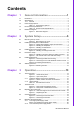
Contents Chapter 1 General Information ............................1 1.1 1.2 Introduction ............................................................................................... 2 Specifications ............................................................................................ 2 1.2.1 General ......................................................................................... 2 Power Supply Options...............................................................................
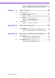
Figure 3.11 Replacing 300W redundant power supply module.. 21 Figure 3.12 Replacing 400W redundant power supply module.. 21 Figure 3.13 Power cord plugs orientation on the socket ............ 22 Chapter 4 Alarm Board ...................................... 23 4.1 Alarm Board Layout ................................................................................ 24 Figure 4.1 Alarm board layout .................................................. 24 Alarm Board Specifications...............................
Chapter 1 1 General Information This chapter provides general information about the IPC-630.
1.1 Introduction The IPC-630 is a 4U-high 15-slot rackmount industrial computer chassis designed for mission-critical applications. It supports either backplane or motherboard. Audible alarm detection and notification with visible LED indicators The IPC-630 comes with an audible alarm module. It automatically detects the system operating conditions, such as power, fan, temperature, and HDD, and displays the system status on the front visible LED indicators.
Table 1.1: Power Supply Options PS-300ATX-ZBE RPS-300ATX-ZE Watt 300 W max. (ATX, PFC) (single PS/2) 300 W max. (ATX, PFC) (1+1 redundant) Input rating 100 ~ 240 Vac (Full range) 100 ~ 240 Vac (Full range) Output voltage +5 V @ 30 A, +3.3 V @ 28 A, +12 V @ 15 A, -5 V @ 0.3 A, -12 V @ 0.8 A, +5 Vsb @ 2 A +5 V @ 25 A, +3.3 V @ 18 A, +12 V @ 16 A, -5 V @ 0.5 A, -12 V @ 0.5 A, +5 Vsb @ 2 A Minimum load +5 V @ 0.1 A, +3.3 V @ 0.3 A +5 V @ 3 A, +3.3 V @ 1 A, +12 V @ 2 A, +5 Vsb @ 0.
1.5 Dimension Diagram Motherboard Backplane Unit: mm [inch] Figure 1.
Chapter 2 2 System Setup This chapter introduces the installation process.
The following procedures guide users to install the backplane, motherboard, add-on cards, and disk drives into the chassis. Please also refer to Appendix A, Exploded Diagram, for the detailed parts of the chassis Note! Use caution when installing or operating the components with the chassis open. Be sure to turn off the power, unplug the power cord and ground yourself by touching the metal chassis before you handle any components inside the machine. 2.1 Removing the Top Cover Please refer to Figure 2.
NUT NUMBER BP/MP MODEL 1 2 3 4 5 6 7 8 9 10 11 12 13 14 15 16 17 18 19 20 21 22 23 24 25 26 27 28 29 X A M PCA-6113P4R PCA-6114P7 PCA-6114P12 PCA-6114P4 PCA-6114P10 PCA-6114-B PCA-6113P7X PCA-6115 PCA-6114P12X PCE-7B13-64 PCE-5B12-64 AIMB-740 AIMB-742 AIMB-744 AIMB-750 AIMB-760 AIMB-762 AIMB-764 AIMB-542 AIMB-554 AIMB-556 AIMB-560 AIMB-562 Be careful to screw the Copper Stub under 10 kgf cm. Figure 2.
Figure 2.3 Installing the backplane Figure 2.
Figure 2.5 Installing a full-length CPU card 9 IPC-630 User Manual System Setup IPC-630 supports up to 15 add-on cards. To install a CPU card or add-on card, please proceed as follows: 1. Select a vacant PICMG slot for the full-length CPU card, or a PCI/ISA slot for other add-on cards. Then, remove the corresponding I/O bracket attached to the rear plate of the chassis. 2.
2.4 Hold-down Clamp The hold-down clamp protects all the cards from vibration and shock. After inserting all the cards, re-fasten the hold-down clamp according to the following steps. 1. There are two rows of notches on both sides of the hold-down clamp for inserting into rubber cushions provided in the accessory. One side is for PCI cards, while the other side is for ISA cards. Depending on the card height, the cushions can be inserted upward or downward.
Figure 2.8 Removing the disk drive housing Figure 2.9 Removing the 3.5" FDD brackets and front covers 11 IPC-630 User Manual System Setup The disk drive housing supports three 5.25" and two 3.5" disk drive devices. Please follow these steps for installation. 1. Undo the four screws on the top of the disk drive housing and then lift it up. (see Figure 2.8) 2. Loosen the two screws on top left of the housing to remove the brackets for fixing the 3.5" FDD or HDD.
Figure 2.10 Installing the disk drives 2.6 Attaching the Ears There is a pair of ears for the front panel in the accessory box. If you need to install the chassis on the rack, please refer to Figure 2.11 to simply fasten them to the frontright and front-left edges with the four screws provided. If you have prepared the slide rails and plan to attach them onto the chassis, please detach the decorated bars on both sides of the chassis first. Figure 2.
Chapter 3 3 Operation This chapter introduces the system operation information.
3.1 The Front Panel The front panel features the lockable door and four LED indicators. The user can close the door with or without the key with the user-friendly rotary lock. When opening the door, there is a System Reset button, an Alarm Reset button, a momentary power switch, a dual USB port and a reserved 9-pin D-SUB opening. The individual functions are described as below. Figure 3.1 Closed Front panel Figure 3.
Switches, Buttons and Front I/O Interfaces Chapter 3 3.1.1 Operation Figure 3.3 Switch, buttons and front I/O interfaces Three switches are located on the front plate, behind the front door. System Reset button: Press this button to reboot the system. Alarm Reset button: Whenever a fault occurs in the system (e.g., fan failure or the temperature in the chassis is too high), an audible alarm will be activated. Pressing this button will stop the alarm from beeping.
3.1.2 LED indicators Four LEDs (see Figure 3.4 above) are placed on the left side of the front panel on the IPC-630 chassis to indicate system health and activity. Please refer to Table 3.1 for the LED definition summary. Table 3.
For the backplane version, the rear plate includes with 15-slot I/O brackets and a reserved 9-pin D-SUB opening. (see Figure 3.4). For the motherboard version, the rear plate includes with 7-slot I/O brackets, 5 reserved 9-pin D-SUB openings and a 68-pin SCSI opening. (see Figure 3.5). Chapter 3 3.2 The Rear Panel Operation Figure 3.4 Rear panel of backplane version Figure 3.5 Rear panel of motherboard version There is a ground screw with a washer located on the lower right of the rear panel.
3.3 Replacing the Cooling Fan There is one cooling fan located on the front left of the chassis. The fan provides the system with ample cooling by blowing air toward the rear. If the fan fails, the alarm will beep. Simply press the Alarm Reset button to stop the alarm and replace the failed fan right away. Please proceed according to the instructions below. 1. Remove the top cover. 2. Unplug the fan power connector. 3. Undo the screw on top of the fan module and take the fan module out. (see Figure 3.6) 4.
Figure 3.8 Removing the front door filter Figure 3.9 Removing the fan filter 19 IPC-630 User Manual Operation The filter prevents dust or particles from entering the work environment and extends longevity of the system. It's better to clean the filters periodically. There are two reusable filters behind the front door and the left front of the chassis. To remove and clean the filter, proceed as follows. 1. Open the front door. 2.
3.5 Replacing the Power Supply The IPC-630 supports either a PS/2 single power supply or a redundant power supply. To replace the power supply, please proceed: 3.5.1 The single power supply model To replace the single power supply, please follow these instructions: 1. Unplug the power cord from the power supply. 2. Remove the top cover and the hold-down clamp. 3. Unplug the 20-pin (or 24-pin) ATX power connector and 4-pin +12V power connector from the backplane.
The redundant power supply model Figure 3.11 Replacing the 300W redundant power supply module Figure 3.12 Replacing the 400W redundant power supply module 21 IPC-630 User Manual Operation In this configuration, there is a redundant power supply with two modules which are hot-swappable. To replace the redundant power supply module, please follow these instructions: 1. Turn off the power switch of the failed power supply module. Then loosen the screw on it and then grab the handle to gently pull it out.
Note! When you plug two power cords into the same bank of sockets, please align them in the same direction (see Figure 3.13). Figure 3.
Chapter 4 4 Alarm Board This chapter introduces the alarm board and thermal sensor specifications.
The alarm board is located under the system fan. The alarm board makes an audible alarm if: ! Any power supply module of redundant power supply fails ! The system fan fails ! Internal temperature of the chassis rises too high To stop the alarm beep, simply press the Alarm Reset button on the front panel. 4.1 Alarm Board Layout The layout and detailed specifications of the alarm board are given below: Figure 4.1 Alarm board layout 4.
CN5: Power LED connector Pin 1 Power Good Power Fail Pin 2 TEMP Fail Pin 2 Fan Fail Pin 2 GND CN6: Temperature LED connector Pin 1 TEMP Good CN7: Fan LED connector Pin 1 Fan Good CN8: HDD LED connector Pin 1 HDD CN13: Voltage detect input connector Pin 1 5 VSB Pin 5 +5 V Pin 2 GND Pin 6 +3.
4.3 Jumper Settings Table 4.2: J2, PIC Clear jumper Normal Open (default) Clear Short Table 4.3: J3, Thermal Sensor jumper One sensor Open (default) Disable Short Table 4.4: J4, Fan Option jumper One fan Open (default) Two fans Short 4.4 Thermal Sensor There is a thermal sensor near the left rear of the chassis. Please refer to Figure 4.2 to find the location. thermal sensor Figure 4.
Appendix A A Exploded Diagrams
A.1 Exploded Diagram Figure A.
Appendix A Exploded Diagrams Figure A.
IPC-630 User Manual 30
Appendix B B Backplane and Motherboard Options
B.1 Backplane Options IPC-630 supports a variety of up to 15-slot backplanes. Users can contact a local sales representative for detailed specification and information. Table B.1: PICMG 1.3 Backplane options Model Name Segment PCE-7B13 PCE-5B12 Slots SHB* PCIe x16 PCIe x 8 PCI-X PCI Single 1 - 2 6 4 Single 1 1 - 6 4 *SHB: System Host Board Table B.2: PICMG 1.
IPC-630 supports a variety of Advantech ATX/microATX motherboards as below. You can contact a local sales representative for detailed information. Table B.
www.advantech.com Please verify specifications before quoting. This guide is intended for reference purposes only. All product specifications are subject to change without notice. No part of this publication may be reproduced in any form or by any means, electronic, photocopying, recording or otherwise, without prior written permission of the publisher. All brand and product names are trademarks or registered trademarks of their respective companies. © Advantech Co., Ltd.