
User manual

IPC-630 User Manual 16
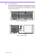
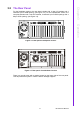
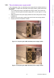
3.1.2 LED indicators
Four LEDs (see Figure 3.4 above) are placed on the left side of the front panel on the
IPC-630 chassis to indicate system health and activity. Please refer to Table 3.1 for
the LED definition summary.
When the system powers is on, the power LED is always Green.
When the power LED is RED, it indicates a redundant power supply module failure.
To stop the alarm beep, press the Alarm Reset button. Examine the redundant
power supply module right away and replace the failed module with a good one.
When the fan LED is RED, it indicates a failed cooling fan, and the alarm is also acti-
vated. To stop the alarm beep, press the Alarm Reset button and then replace the
failed fan with a good one immediately.
If the temperature LED is RED, it means that inside of the chassis is overheated. An
audible alarm will be activated. Press the Alarm Reset button to stop the alarm beep.
Inspect the system fan and its filter and the rear of the chassis immediately. Make
sure the airflow inside the chassis is smooth and not blocked by dust or other parti-
cles.
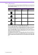
Table 3.1: LED indicator functions
LED Description Green Red
Power System power Normal Abnormal
Fan Cooling fan status Normal Abnormal
Temperature Temperature in the
chassis
Normal Abnormal
Hard Disk Hard disk drive activ-
ity
Data access No light