User Manual ACP-1010 1U Rackmount Chassis for ATX / MicroATX Motherboard or SHB / SBC
Copyright The documentation and the software included with this product are copyright 2009 by Advantech Co., Ltd. All rights are reserved. Advantech Co., Ltd. reserves the right to make improvements in the products described in this manual at any time without notice. No part of this manual may be reproduced, copied, translated or transmitted in any form or by any means without the prior written permission of Advantech Co., Ltd. Information provided in this manual is intended to be accurate and reliable.
Safety Instructions 1. 2. 3. 4. 5. 6. 7. 8. 9. 10. 11. 12. 13. 14. 15. 16. 17. Read these safety instructions carefully. Keep this user manual for later reference. Disconnect this equipment from AC outlet before cleaning. Do not use liquid or spray detergents for cleaning. For pluggable equipment, the power outlet shall be installed near the equipment and shall be easily accessible. Keep this equipment away from humidity. Put this equipment on a reliable surface during installation.
18. This device complies with Part 15 of the FCC rules. Operation is subject to the following two conditions: (1) this device may not cause harmful interference, and (2) this device must accept any interference received, including interference that may cause undesired operation. 19. CAUTION: Always completely disconnect the power cord from your chassis whenever you work with the hardware. Do not make connections while the power is on. Sensitive electronic components can be damaged by sudden power surges.
Product Warranty (2 years) Advantech warrants to you, the original purchaser, that each of its products will be free from defects in materials and workmanship for two years from the date of purchase. This warranty does not apply to any products which have been repaired or altered by persons other than repair personnel authorized by Advantech, or which have been subject to misuse, abuse, accident or improper installation.
Initial Inspection When you open the carton, please make sure that the following materials have been shipped: ! ACP-1010 Chassis ! User Manual ! Warranty Card ! Accessory box with a package of screws (for fastening the backplane / motherboard, disk drives), two M/B I/O shields for ACP-1010MB. If any of these items are missing or damaged, contact your distributor or sales representative immediately. We have carefully inspected the ACP-1010 mechanically and electrically before shipment.
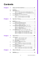
Contents Chapter 1 General Information ............................1 1.1 1.2 1.3 Introduction ............................................................................................... 2 Specifications ............................................................................................ 2 Power Supply Options............................................................................... 3 Table 1.1: Power supply options for BACKPLANE version ......... 3 Table 1.
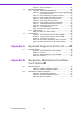
4.3 4.4 Figure 4.1 Alarm board layout ................................................... 22 Alarm Board Specifications..................................................................... 22 4.3.1 Connector, Jumper and Pin Definitions ...................................... 23 Table 4.1: CN1, Auxiliary external power connector, standard mini 4-Pin power connector ............................................. 23 Table 4.2: CN4, Thermal sensor (LM75) connector .................. 23 Table 4.
Chapter 1 1 General Information This chapter provides general information about the ACP-1010.
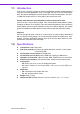
1.1 Introduction ACP-1010 is a compact, rugged 19” rackmount industrial computer chassis designed for space-conscious applications. Only 1U in height, the ACP-1010 can accept versatile 3-slot passive backplanes and two full-size PCI cards via backplanes. The ACP1010MB can accept one PCI or PCIe add-on card via the riser card. Unique alarm detection and notification to reduce system down time ACP-1010 has a unique alarm module.
Table 1.1: Power supply options for BACKPLANE version 1757001797 1757000160G Watt 250 W max. (ATX, PFC) (single power) 300 W (ATX, PFC) (single power) Input Rating 100 ~ 240 Vac (Full range) 100 ~ 240 Vac (Full range) Output Voltage +5 V @ 23 A, +3.3 V @ 14 A, +12 V @ 16 A, -12 V @ 0.5 A, -5 V @ 0.2 A, +5 Vsb @ 2 A +5 V @ 25 A, +3.3 V @ 14 A, +12 V @ 16 A, -12 V @ 1 A, -5 V @ 0.5 A, +5 Vsb @ 2 A Minimum Load +5 V @ 3 A, +3.3 V @ 1 A, +12 V @ 2 A, -12 V @ 0.1 A, -5 V @ 0 A, +5 Vsb @ 0.
1.5 Dimension Diagram unit: mm [inch] Figure 1.1 Dimension diagram for ACP-1010BP unit: mm [inch] Figure 1.
Chapter 2 2 System Setup This chapter introduces the installation process.
2.1 Introduction The following procedures are provided to assist you in installing a backplane, CPU card, motherboard, riser card, disk drives, and add-on cards into the chassis. Please also refer to the Appendix A, Exploded Diagram, for the parts naming in this manual. 2.2 Removing the Top Cover To remove the top cover of the ACP-1010, please refer to Figure 2.1. Remove screws; slide cover back; lift cover up. Figure 2.
ACP-1010 accepts a 3-slot backplane. To install the backplane, refer to the figures and proceed as follows: Note! 2. 3. 4. 5. 6. Remove the backplane (T-bar) holder and then fix the backplane onto it with screws. (Figure 2.2) Insert the CPU card (with CPU, cooler, RAM and necessary cables installed) into the slot on the backplane. Then fasten the card guide with screws. (Figure 2.3) Insert the PCI/PCIe add-on card to the proper slot on the backplane and then fixed it solidly.
Figure 2.
Figure 2.4 Yellow label indicating stand-off locations Figure 2.5 Stand-off spacer 2. 3. 4. 5. The accessory attaches 2 motherboard I/O shields. Choose the correct one to be installed on the rear plate of the chassis. Fix the motherboard in the chassis with screws. Plug in the 20/24-pin ATX power connector and +12 V power connector from the power supply, also the 9-pin USB connectors from the front panel of the chassis.
Figure 2.6 Installing a motherboard 6. 7. If customer purchases a riser card, then insert it on the 6th slot of the ATX motherboard or the 3rd slot of the microATX motherboard. Insert the add-on card to the slot on the riser card, then fasten it to the rear plate of the chassis. Figure 2.
Figure 2.8 Small converter for ATA (IDE) slim-type ODD Figure 2.9 Installing a slim ODD & HDD / FDD 11 ACP-1010 User Manual System Setup ACP-1010 comes with two 3.5" disk drive bays for HDD and FDD. It also accepts one slim type optical disk drive. To install any of these disk drives, please proceed as follows: 1. Open the front cover by pushing the latches. 2. Remove the four screws, which mount the slim-type optical disk drive and 3.5” HDD brackets on the chassis. 3.
Figure 2.10 Installing a 3.5" or 2.5" HDD in ACP-1010BP Figure 2.11 Installing a 3.5" or 2.
Chapter 3 3 Operation This chapter introduces system operation information.
3.1 The Front Panel The front panel features six LED indicators. The door is fitted with a user-friendly latch. When the door is open, one sees a momentary power switch, a System Reset button, an Alarm Reset button, and a dual USB port. Their individual functions are described below. Figure 3.1 Front view with door closed Figure 3.2 Front view with door open 3.1.1 Switch, Button and I/O Interfaces Momentary Power switch: Press this switch to turn the system power on or off.
Six LEDs are placed in the middle of the front panel to indicate system health and activity. Please refer to Table 3.1 for the LED definition summary. Table 3.1: LED indicator functions LED Description Green Red Orange System power Normal N/A N/A Cooling fan status Normal Abnormal N/A Temperature in the chassis Normal Abnormal N/A Hard disk drive activity N/A No light Normal LAN1 & LAN2 status Normal No light N/A Chapter 3 3.1.
3.2 Replacing the Cooling Fan There are three cooling fans located near the front, and one located near the rear of the ACP-1010BP chassis; and there are two fans close to the rear window of the ACP-1010MB chassis. To replace a cooling fan, please proceed as below. 1. Un-plug the fan power connector. 2. Remove the screws which mount the fan bracket on the chassis, and take it out. 3. Remove the guard that protects the failed fan. 4.
The filter blocks dust or particles from the work environment and helps extend the longevity of the system. It’s better to clean the filters periodically. There is an easy-tomaintain filter behind the front cover. To replace the filter, proceed as follows. 1. Open the front cover. 2. Unscrew the filter cover by loosening the screws. (see Figure 3.5) 3. Replace it with a new one. Then return the filter cover and fasten it. Chapter 3 3.3 Replacing the Filter Operation Figure 3.
3.4 Replacing the power supply ACP-1010 supports a single, 1U power supply. To change the power supply, please proceed as follows: 1. Un-plug the AC inlet from the power supply. 2. Remove the top cover. 3. Unplug the ATX power connector and +12V power connector from the CPU card / motherboard, and the peripheral power connector(s) from the drive disk(s). 4.
Chapter 3 Operation Figure 3.
ACP-1010 User Manual 20
Chapter 4 4 Alarm Board This chapter introduces the alarm board and thermal sensor specifications. Sections include: ! Alarm board layout ! Alarm board specifications ! Thermal sensor ! Sensor I.D.
4.1 Introduction The alarm board is located in the middle section, between the driver bay and the power supply. The alarm board gives an audible alarm when: ! A cooling fan fails ! Chassis internal temperature is too high To stop the alarm beep, simply press the Alarm Reset button on the front panel, then take the necessary actions to remedy the situation. 4.2 Alarm Board Layout The layout and detailed specifications of the alarm board are given below: Figure 4.1 Alarm board layout 4.
Table 4.1: CN1, Auxiliary external power connector, standard mini 4-Pin power connector Pin 1 +12 V Pin 3 GND Pin 2 GND Pin 4 +5 V Chapter 4 4.3.1 Connector, Jumper and Pin Definitions Table 4.2: CN4, Thermal sensor (LM75) connector +5 V Pin 3 T_SDAT Pin 2 T_SCLK Pin 4 GND Table 4.3: CN13, Voltage detect input connector Pin 1 +5 Vsb Pin 5 +5 V Pin 2 GND Pin 6 +3.3 V Pin 3 GND Pin 7 -12 V Pin 4 -5 V Pin 8 +12 V Table 4.
4.3.2 Switch Settings The alarm board is designed to connect with up to 7 fans. The number of fans connected should be set by adjusting switch SW1 on the alarm board. Table 4.11: SW1.
Chapter 4 Alarm Board Figure 4.3 Thermal sensor location in ACP-1010MB Figure 4.
The default sensor I.D. number is 1. Please refer to Table 4.13 to set the sensor I.D. to another number by adjusting switch SW1 on the sensor module. Table 4.12: CN1 & CN2, Temperature sensor connector Pin 1 +5 V Pin 3 T_SDAT Pin 2 T_SCLK Pin 4 GND Table 4.13: SW1, Thermal sensor I.D. number settings Sensor I.D. No.
Appendix A A Exploded Diagram & Parts List
A.1 Exploded Diagram Figure A.1 Exploded Diagram of ACP-1010BP Table A.1: Parts List 1 Top cover 2 T bar support 18 Fan holder I 3 HDD rubber 19 System fan x 1(40*15mm) 4 Front panel 20 Card Guide holder 5 Driver Bay 21 PCB guide rail 6 Slim ODD cover 22 Chassis 7 3.
Table A.2: Parts List 1 Front door 11 2 Alarm Reset switch 12 USB Cable 3 System Reset switch 13 Thermal sensor 4 Power switch 14 Switch holder 5 3.5” drive front cover 15 Rack mount bracket 6 Slim ODD front cover 16 Fan 7 Drive bay 17 Fan holder 8 HDD bracket 18 Power supply 9 Top cover 19 Chassis base 10 Alarm board 29 LED housing ACP-1010 User Manual Appendix A Exploded Diagram & Parts List Figure A.
ACP-1010 User Manual 30
Appendix B B Backplane, Motherboard and Riser Card Options
B.1 Backplane Options ACP-1010 supports a variety of PICMG 1.0/1.3 backplanes. Please contact a local sales representative for detailed information. Table B.1: PICMG1.3 Backplane Options Slots Model Name SHB* PCIe x 16 PCIe x 4 PCI PCE-5B03V-01A1E 1 1 - 1 PCE-5B03V-00A1E 1 1 1 - *System Host Board Table B.2: PICMG1.0 Backplane Options Slots Model Name PICMG PCI PCI-X 1 2 - PCA-6103P2V-0A2E B.2 Motherboard and Riser Card Options Table B.
Bus Model Name PCI AGP SATA AIMB-556 1 (PCIe x16) 1 (PCIe x4) 2 (PCI 32-bit) - 3 AIMB-554 1 (PCIe x16) 1 (PCIe x4) 2 (PCI 32-bit) - 2 AIMB-552 3 (PCI 32-bit) - 2 Table B.
www.advantech.com Please verify specifications before quoting. This guide is intended for reference purposes only. All product specifications are subject to change without notice. No part of this publication may be reproduced in any form or by any means, electronic, photocopying, recording or otherwise, without prior written permission of the publisher. All brand and product names are trademarks or registered trademarks of their respective companies. © Advantech Co., Ltd.