
User manual


ASMB-922I User Manual 20
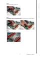
2.8 Front Panel Connector (JFP1)
There are several external switches and LEDs to monitor and control the ASMB-922I.
2.8.1 Power LED (JFP3)
JFP3 pin 1 and pin 3 are for the power LED. Refer to Appendix B for detailed infor-
mation on the pin assignments. If an ATX power supply is used, the system’s power
LED status will be as indicated as follows.
2.8.2 External Speaker (JFP2 pins 1, 4, 7, 10)
JFP2 pins 1, 4, 7, 10 connect to an external speaker. The ASMB-922I provides an
onboard buzzer as an alternative. To enable the buzzer, set pins 7-10 closed.
Table 2.3: ATX Power Supply LED Status
ACPI Power Mode LED (ATX power)
System On (S0) On
System Standby (S1) Fast flashes
System Hibernation(S4) Slow flashes
System Off (S5) Off
1
23
+
-