EDG-6528 8-Port Industrial 10/100 Mbps Ethernet Switch User Manual
Copyright The documentation and the software included with this product are copyrighted 2005 by Advantech Co., Ltd. All rights are reserved. Advantech Co., Ltd. reserves the right to make improvements in the products described in this manual at any time without notice. No part of this manual may be reproduced, copied, translated or transmitted in any form or by any means without the prior written permission of Advantech Co., Ltd. Information provided in this manual is intended to be accurate and reliable.
Product Warranty (2 years) Advantech warrants to you, the original purchaser, that each of its products will be free from defects in materials and workmanship for two years from the date of purchase. This warranty does not apply to any products which have been repaired or altered by persons other than repair personnel authorized by Advantech, or which have been subject to misuse, abuse, accident or improper installation.
CE This product has passed the CE test for environmental specifications. Test conditions for passing included the equipment being operated within an industrial enclosure. In order to protect the product from being damaged by ESD (Electrostatic Discharge) and EMI leakage, we strongly recommend the use of CE-compliant industrial enclosure products. FCC Class A This equipment has been tested and found to comply with the limits for a Class A digital device, pursuant to Part 15 of the FCC Rules.
Contents Chapter 1 Introduction ..................................................... 2 1.1 1.2 1.3 1.4 1.5 1.6 Chapter Features ............................................................................. 2 Feature Summary .............................................................. 3 Specifications .................................................................... 4 Packing List....................................................................... 4 Ordering Information ..........................
EDG-6528 User Manual vi
CHAPTER 1 2 Introduction Sections include: • Features • Specifications • Packing List • Ordering Information • Safety Precaution
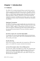
Chapter 1 Introduction 1.1 Features The EDG-6528 is an industrial-grade Ethernet switch for fast and costeffective expansion of industrial Ethernet networks. The EDG-6528 has eight 10/100 Mbps Ethernet ports to connect up to eight Ethernet devices. Moreover, EDG-6528 has industrial-grade design that assures high reliability and stability.
Wide Operating Temperature Range The operating temperature of the EDG-6528 is between 0 and 70° C, and the EDG-6528I can operate between -40 and 85° C. With such a wide range you can use the EDG-6528 in some of the harshest industrial environments that exist. Easy to Trouble-Shoot LED indicators make troubleshooting quick and easy. Each port has LEDs that display the link status, power failure, and port activity for immediate on-site diagnosis. (See 2.1) 1.
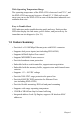
1.3 Specifications • Interfaces: Network 10/100Base-Tx standard • Ports: 8 x 10/100 Mbps (RJ-45) • Connectors: 8 x RJ-45 • Compatibility: IEEE 802.3, IEEE 802.3u • Surge Protection: 3000 VDC (Power) • ESD Protection: 4000 V DC (Ethernet)(not including EDG-6528L) • LEDs: Power, LNK/ACT, 10/100 Mbps • Transmission Distance: 100 m (Ethernet) • Power Requirement: Unregulated 12~48 VDC • Power Consumption: Max. 3.
1.6 Safety Precaution Attention! If DC voltage is supplied by an external circuit, please use a protection device on the power supply input.
EDG-6528 User Manual 6
CHAPTER 2 2 Installation In this chapter, you will be given an overview of the EDG-6528 installation procedure.
Chapter 2 Installation 2.1 LED Definitions There are network status LEDs located on the front panel of EDG-6528, each with its own specific meaning.. Table 2.
2.2 Dimensions Figure 2.
2.3 Mounting 2.3.1 Panel Mounting • Attach the bracket to the EDG-6528 with four screws. • Place the EDG-6528 against the panel or wall, and fasten it by using two screws in the bracket’s holes. Figure 2.2: Attach the Bracket to the EDG-6528 with Six Screws Figure 2.
2.3.2 DIN-rail Mounting 1. Attach the DIN-rail mounting kit to the EDG-6528 with six screws. Figure 2.4: Attach the DIN-rail Mounting Kit to EDG-6528 with Six Screws 2. Snap the EDG-6528 onto the DIN rail to attach it. Figure 2.5: DIN-rail Mounting.
2.3.3 DIN-rail Dismounting Use a flat screwdriver to lift the DIN rail’s attachment bracket up. This will release the EDG-6528 from the Din-rail. Then pull the EDG-6528 down to dismount it. Figure 2.
2.4 Network Connections 2.4.1 Connection to Devices Each of the switch’s twisted-pair ports can be used to connect a station or another device. Use a straight-through twisted-pair cable with RJ-45 connectors on both ends. A twisted-pair cable extended from a twisted-pair port is called a “twisted-pair segment,” and it can be up to 100 meters long. You can connect any RJ-45(MDI-X) station port on the switch to any device that uses a standard network interface such as a workstation or server. 2.4.
2.5 Power Connections EDG-6528 and EDG-6528I support two individual power inputs (P1/P2); it will switch to another power input if one power input fails. Pin Description +Vs Power input 1 (Range: +12~48VDC) +Vs* Power input 2 (Range: +12~48VDC) GND Power ground Relay out (EDG-6528L does not have this function) You can connect to an alarm such as an indicator, buzzer or other signaling equipment by EDG-6528’s relay output. The relay opens if power input 1 or power input 2 fails.