User Manual EKI-152X series 1/2/4-port RS-232/422/485 Serial Device Servers
Copyright The documentation and the software included with this product are copyrighted 2010 by Advantech Co., Ltd. All rights are reserved. Advantech Co., Ltd. reserves the right to make improvements in the products described in this manual at any time without notice. No part of this manual may be reproduced, copied, translated or transmitted in any form or by any means without the prior written permission of Advantech Co., Ltd. Information provided in this manual is intended to be accurate and reliable.
Declaration of Conformity CE This product has passed the CE test for environmental specifications when shielded cables are used for external wiring. We recommend the use of shielded cables. This kind of cable is available from Advantech. Please contact your local supplier for ordering information. CE This product has passed the CE test for environmental specifications. Test conditions for passing included the equipment being operated within an industrial enclosure.
6. Put this equipment on a reliable surface during installation. Dropping it or letting it fall may cause damage. 7. The openings on the enclosure are for air convection. Protect the equipment from overheating. DO NOT COVER THE OPENINGS. 8. Make sure the voltage of the power source is correct before connecting the equipment to the power outlet. 9. Position the power cord so that people cannot step on it. Do not place anything over the power cord. 10.
Contents Chapter Chapter 1 Overview...............................................1 1.1 1.2 1.3 1.4 Introduction ............................................................................................... 2 Features .................................................................................................... 3 Specifications ............................................................................................ 3 Package Check List .......................................................
3.3 3.4 3.5 3.6 3.7 3.8 3.9 Chapter Network Settings..................................................................................... 27 Serial Settings......................................................................................... 29 Operation Mode Settings ........................................................................ 33 3.5.1 Virtual COM Mode ...................................................................... 33 3.5.2 Data Mode (USDG Mode) ..................................
Chapter 1 Overview 1
1.1 Introduction Advantech's EKI-1521, EKI-1522, and EKI-1524 series of Industrial Device Servers (the following manual will use EKI-152X series instead of complete model name) are a robust, feature-rich, and cost effective way to network-enable equipment in an industrial automation environment.
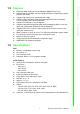
1.3 Specifications LAN Ethernet: 10/100 Mbps auto sensing No. of Ports: 2 Port Connector: RJ45 Protection: Built-in 1.5 KV magnetic isolation Serial Interface Interface: RS-232/422/485, software selectable No. of Ports: – EKI-1521: 1 – EKI-1522: 2 – EKI-1524: 4 Port Connector: DB9 male Baud Rate: 50 bps to 921.6 Kbps Parity: None, Even, Odd, Space, Mark Data bits: 5, 6, 7, 8 Stop bits: 1, 1.
Software Utility: Advantech Serial Device Server Configuration Utility Driver support: Windows 2000/XP/Vista/7, Windows Server 2003/2008, Linux Operation Mode: – COM port redirection (Virtual COM) – TCP/UDP server (polling) mode – TCP/UDP client (event handling) mode – Pair connection mode Configuration: Web interface, Windows utility, Telnet console Protocol: ICMP, IP, TCP, UDP, BOOTP, DHCP, Auto IP, Telnet, SNMP, HTTP, DNS, SMTP, ARP, NTP Management: SNMP MIB-II General LED indicators: – Sys
Chapter 2 Getting Started 2
2.1 Understanding EKI-152X series The EKI-152X series are network-based, serial device servers for connecting RS232/422/485 devices, such as CNCs, PLCs, scales, and scanners, directly to a TCP/ IP network. Once connected through EKI-152X series, the serial device will be able to send and receive data on a network like any other network device. It extends traditional COM ports of a PC with access over a TCP/IP network.
Advantech Serial Device Server Configuration Utility is a serial COM port redirector that creates virtual COM ports and provides access to serial device connected to Advantech serial device server. You can configure the serial device server and enable the Virtual COM port using one integrated utility.
2.1.2.2 Multi-Access Mode (Shared COM port mode) Most of serial devices are connected directly and physically to the PC serial ports via a cable. The operation system, ex. Windows XP, provides the COM ports that user’s application can access, and control the serial device through the serial cable. This means that the serial device can be connected to one host and only one application on this host can handle input, output and control operation on this device.
In TCP server mode, you might initiate the TCP connection from host to EKI serial device server. This operation mode support max. five simultaneous connections for each serial port on EKI serial device server from one host or several hosts, however multi-hosts collect the data from one serial port at the same time Chapter 2 2.1.3 TCP Server Mode Getting Started Figure 2.4 TCP Server Mode 2.1.4 TCP Client Mode In TCP Client mode, the TCP connection will be established from EKI serial device server.
2.1.5 Serial Tunneling Mode Two native serial devices can communicate over an Ethernet network without any intermediate host PC and software programming. Serial Tunneling is very simple to use. You can use Advantech Serial Device Server Configuration Utility to designate one serial port as the tunneling master and another serial device server port as the tunneling slave. Figure 2.6 Serial Tunneling Mode 2.1.6 UDP Server/Client Mode UDP is used primarily for broadcasting messages over a network.
In this section, we will give you an overview of EKI-152X series hardware and installation. 2.2.1 LED Indicators There are LEDs display the power status, network status, and serial communication status located on the front panel of EKI-1521, EKI-1522, and EKI-1524, each of them has its own specific meaning as below table. LED Name P1 P2 Status Ethernet Serial LED Color LED Description Green Power 1 is on. Off Power 1 is off, or power error condition exists. Green Power 2 is on.
2.2.2 Dimensions (Units: mm) 2.2.2.1 EKI-1521 and EKI-1522 Figure 2.7 Front View of EKI-1521/1522 Figure 2.
Chapter 2 Getting Started Figure 2.9 Back View of EKI-1521/1522 Figure 2.
2.2.2.2 EKI-1524 Figure 2.11 Front View of EKI-1524 Figure 2.
Chapter 2 Getting Started Figure 2.13 Back View of EKI-1524 Figure 2.14 Top View of EKI-1524 2.3 Connecting Hardware Next, we will explain how to find a proper location for your EKI-152X series, and then explain how to connect to the network, hook up the power cable, and connect to the EKI-152X series serial port. 2.3.1 Choosing the Location Due to its versatility and innovative design, EKI serial device server can be: Fixed to a panel mount Fixed to a DIN-rail.
2.3.1.1 Panel/Wall Mounting The EKI-152X series can be attached to a wall using the included metal brackets. Each bracket comes with four screws; and then you can install the device firmly via the components, please see the figure as below. Figure 2.15 Combine the Metal Mounting Kit 2.3.1.2 DIN Rail Mounting You can mount the EKI-152X series on a standard DIN-rail. Please screw the DIN-rail kit on the serial device server first. First, hang the EKI-152X series to the DIN-rail with angle of inclination.
Chapter 2 2.3.2 Network Connection EKI-152X series has 2x RJ-45 that support connection to 10 Mbps Ethernet, or 100 Mbps Fast Ethernet, and half or full duplex operation. EKI-152X series can be connected to other hubs or switches through a twisted-pair straight through the cable or a crossover cable up to 100m long. 2.3.3 Power Connection The EKI-152X series supports dual 12 to 48 VDC power inputs and power-fail relay output. Figure 2.
2.3.4 Serial Connection EKI-152X series provides one, two, or four ports DB9 (male) connectors. RS-232/ 422/485 pin assignments as below: Table 2.2: EKI-152X series Serial Pin Assignments Pin 1 2 3 4 5 6 7 8 9 RS-232 DCD RX TX DTR GND DSR RTS CTS RI RS-422 TX- - - TX+ GND - RX+ - RX- RS-485 DATA- - - DATA+ GND - - - - 2.
4. Carefully read the Software License Agreement, and press "Yes" to continue. Getting Started Upon executing the setup program, the Welcome Dialog Box will be pop-up. Press the "Next" button to continue. Chapter 2 3.
5. The Setup program will specify a default installation path: C:\Program Files\Advantech eAutomation\Serial Device Server Configuration Utility\ 6. After setup has copied all program files to your computer, click the button to finish the installation.
Chapter 3 Configuration 3
3.1 Configuration Utility Overview EKI-152X series serial device servers provide an easy-to-use utility to configure your serial device server through an Ethernet connection. For secure administration, it can also restrict the access rights for configuration to only one host PC. With this secure function enabled, other PCs will not have permission for configuration.
Please reserve TCP/UDP port 5048 and 5058 in your Ethernet network, configuration utility will use these ports to communicate with Advantech EKI-1000, ADAM-4570, and EDG-4500 serial device servers. 3.2 Discovering Serial Device Servers Advantech Serial Device Server Configuration Utility will automatically search all the EKI-1000, ADAM-4570 and EDG-4500 series device servers on the network and show them on the Serial Device Server List Area of the utility.
Select the device in this sub-tree. The first tab on the “Configuration Area” shows the summary of “Basic Information” included device type, version, and name, “Ethernet Information”, and “Serial Port Information”. In the serial port information frame, it displays the operation mode, status and connected host IP. Click on the “+” before the device name, and the utility will expand the interfaces on this device server. Click on each item, you will entry the configuration page to change the setting.
Chapter 3 Configuration 3.2.2 Clear Device List and Search Again You can click the button on the Quick Tool Bar. The utility will clear all list device servers in the Serial Device Server List Area and re-search again. Don’t use this function frequently. The warning message will be pop-up when you double click this button. You can click the button on the “Quick Tool Bar”. The utility will search serial device server on local LAN.
3.2.3 Manual Appending Using “Add IP address to Favorite” or “Search a Range of IP addresses” function, you are able to add one device or group of devices to “Favorites”. These devices can locate on local network domain or other network domain.
This section explains how to configure the EKI-152X series network using this utility so that it can communicate over a network with serial devices. Click on the “+” before the model name (e.g. EKI-1524), and the utility will expand the tree structure to show the individual device name. And click on the “+” before the device name, and the utility will expand the interfaces on this device server. Select the Ethernet interface. (Select Eth1 or Eth2, these are two individual Ethernet ports) Chapter 3 3.
IP address, Subnet Mask, Default Gateway: You can choose from four possible IP Configuration modes --- Static, DHCP, BOOTP, and DHCP/BOOTP. Static IP User defined IP address, Subnet Mask, and Default Gateway. DHCP + Auto-IP DHCP Server assigned IP address, Subnet Mask, Default Gateway, and DNS. BOOTP + Auto-IP BOOTP Server assigned IP address. DHCP + BOOTP + Auto-IP DHCP Server assigned IP address, Subnet Mask, Default Gateway, and DNS, or BOOTP Server assigned IP address.
This section explains how to configure the EKI-152X series serial communication parameters using this utility. There are various operation modes that are suitable for different application. Description: You can give a more detailed description on the function of the port for easier management and maintenance. Descriptions have a limit of 128 characters. Type The EKI-152X series serial device server offers three kinds of serial interfaces, RS232, RS-485 and RS-422.
Baud Rate: The EKI-152X series serial device server supports baud rate from 50 to 921.6Kbps. While setting the baud rate, please note that the value should conform to the current transmission speeds of connected devices. Parity: The EKI-152X series serial device server provides five options: None, Odd, Even, Space, and Mark. Data Bits: The EKI-152X series serial device server provides four options: 5, 6, 7 and 8. Stop Bits: The EKI-152X series serial device server provides three options: 1, 1.
When you have finished the configuration of these settings for each category, please press the “Apply” button in order to make these settings effective on the Serial Device Server. Or you can press “Apply All Ports” to make these setting effective for all serial ports on the Serial Device Server. Advanced Settings: The EKI-152X series serial device server provides the advanced settings for some special applications which need critical time requirements.
Ignore Purge Some application program will purge the serial port while it is the first time opens this serial port. You can ignore the purge command by enable this option. Disable Character Timeout Detection Enable this option will disable the serial port character timeout detection. Disable Multiple Connection Enable this option will disable the multi-access function, thus the only one TCP connection is allowed on this serial port.
The EKI-152X series provides Multi-access function through Ethernet connection path. Allow the maximum of 5 connections to open one serial port simultaneously. In this mode, all connection has to use the same serial setting. If one serial setting of these connections is different from others, the data communication may operate incorrectly. Host Idle Timeout The "Host Idle Timeout" setting monitors the connection between the host and the device.
nections, so multiple hosts can transmit/receive data to/from the same serial port simultaneously. Every host can transmit data to the same serial port, and the EKI152X series will also transmit data to every hosts. When the multiple hosts transmit data to the same serial port at the same time, the received data from Ethernet and the outputs of serial port are mixed. When the EKI-152X series receives data from serial port, the data will also be transmitted to the connected hosts simultaneously.
Chapter 3 Configuration Protocol The EKI-152X series provides TCP/IP and UDP two protocols. In settings, you can choose either TCP mode or UDP mode according to your application. Data Listen Port The TCP/UDP port number represents the source port number, and the number is used to identify the channel for remote initiating connections. Range: 1024-65533. If an unknown caller wants to connect to the system and asks for some services, they need to define the TCP/UDP port to carry a long-term conversation.
time, the EKI-152X series will disconnect temporarily. When the data comes to the EKI-152X series, it will reconnect automatically. Users do not need to reconnect. Enable Time Sharing The EKI-152X series provides Multi-access function through Ethernet connection path. Allow the maximum of 5 connections to open one serial port simultaneously. In the mode, all connection has to use the same serial setting.
Chapter 3 Set the number of network device which you want to connect. You can set maximum sixteen network devices which you want to connect. You need to fill out the IP Address and Port (including local port and peer port) of network devices which you want to connect. Configuration Data Pack Data pack means you can set condition of receiving data from serial port to be a package according to your application.
networking device. If you want serial device running application program to connect/ disconnect to different devices dynamically, you can use controlling mode. The “Control mode” provides three kinds of modem AT-style commands. The serial devices can use these commands to control the EKI-152X series to connect/disconnect to remote networking device. Thus, intelligent serial devices such as standalone PLC will send /receive data to/from devices one by one via Ethernet.
DISCONNECT Disconnect from other device ERROR Incorrect commands FAIL If you issu an ATDT command and can not connect to the device, it will response “FAIL”. Chapter 3 RING ddd.ddd.ddd < Detect the connection request from other device, CR> which IP address is ddd.ddd.ddd.ddd. Configuration 3.6 Accessible IP Settings Accessible IP setting allows you to add or remove the blocking host IP addresses to prevent unauthorized access.
3.7 Auto Warning Settings 3.7.1 Email Alert Consult your ISP or Network Administrator for the proper SMTP mail server settings. The auto warning functions may not work properly without proper settings. 3.7.2 SNMP Trap You need to set the proper IP address of SNMP Trap Server. And choose the Trap Version; there are “SNMP v1” and “SNMP v2c” options.
Chapter 3 3.7.3 System Event Configuration Cold Start This refers to starting the system from power off. When performing a cold start, the EKI-152X series will send an e-mail, or send a SNMP trap after success rebooting. Warm Start This refers to restarting the system without turning the power off. When performing a warm start, the EKI-152X series will send an e-mail, or send a SNMP trap after restarting the system. Authentication failure The user types a wrong password from Console or Administrator.
Ethernet 2 Down The Ethernet 2 port has link failure condition. When the Ethernet 2 links fail, the EKI152X series will send an e-mail, or send a SNMP trap immediately. 3.7.4 Serial Port Event DCD Change The DCD (Data Carrier Detect) signal has changed, also indicating that the modem connection status has changed. For example, a DCD change to high also means “Connected” between local modem and remote modem. If the DCD signal changes to low, it also means that the connection line is down.
Chapter 3 Configuration 3.9 Administrator Settings The configuration utility provides several administrator settings for easy management and configuration. Right click the mouse on the device name in the sub-tree of Serial Device Sever List Area, and select these administrator settings.
3.9.1 Import/Export Device Setting The utility allows importing or exporting the serial device server’s setting via the “.conf” file format. 3.9.2 Import/Export Serial Port Setting The utility allows importing or exporting the serial port setting including “Basic Setting” and “Operation Setting” via “.sps” file format.
Chapter 3 Configuration 3.9.3 Locate the Serial Device Server If there are many serial device severs need your management, you may need to identify which unit is correct to configuration on utility. Click “Locate” to make that unit’s “Status” LED be steady on and the buzzer will make the beep sound until you click “Stop Locate”. 3.9.4 Lock the Serial Device Server (Password Protection) The configuration utility provides the “Lock Device” function to make it more confidential.
Click “Unlock Device” to unlock the serial device sever, and you need to fill in the password you have set up before. If you forgot the password, the only way to solve this problem is to restore the setting of the serial device server to the factory default which will be introduced next section.
Chapter 3 Configuration 3.9.5 Restore to Factory Default Settings The configuration utility provides this function to let you can restore the serial device server to factory default settings. The confirm message will be pop-up while clicking “Restore to Factory Default Settings”. If you really want to restore the serial device sever to factory default settings, please click “Yes” button to continue.
3.9.6 Update Firmware Advantech continually upgrades its firmware to keep up with the ever-expending world of computing. You can use the update firmware function in the utility to carry out the upgrade procedure. Please access Advantech’s website: http://www.advantech.com to download the latest version of the firmware. Before update the firmware, make sure that your host’s Network domain is as same as the serial device server or the host can establish the TCP connection to the serial device server.
Be sure that the host PC Ethernet network domain is as same as the EKI-152X series serial device server or the host PC can establish the TCP connection with the serial device server while doing the updating firmware process. 49 EKI-1521/1522/1524 User Manual Configuration Note! Chapter 3 Wait for few seconds to process the updating firmware. After downloading the firmware completely, click on the “OK” button. The serial device server will restart automatically.
EKI-1521/1522/1524 User Manual 50
Chapter 4 Setting COM Redirector 4
4.1 Setting COM Redirector (Virtual COM port) Advantech COM port mapping software is a serial COM port redirector that creates virtual COM ports and provides access to serial devices connected to Advantech serial device servers. Your serial device applications can communicate with serial devices connected to Advantech serial device servers without software changes.
Chapter 4 53 EKI-1521/1522/1524 User Manual Setting COM Redirector The COM ports in the “Virtual Com Ports” listing are now available for use by Windows applications.
4.1.2 Manual Mapping Right click the serial device name on the sub-tree of Device Server List area and select the “Manual Mapping” function. ADAM series, EDG series, and EKI wireless series have only one IP address. Select the serial port on the device server and the host COM that you want to set. Press
EKI-152X series has two Ethernet ports. You can select two Ethernet port to establish two Ethernet connections with one virtual COM port. It means that COM redirector will use one connection with the COM port on device server to communicate. If this connection failed, COM redirector will establish another Ethernet connection to communicate with device. The switch time will be 3 seconds ~ 5 seconds depending on the network traffic and host status.
4.1.3 Manual Direct Mapping Virtual COM Port Click the button on the Quick Took area, you can add a target by selecting the Device Type and inputting the IP address without physically connecting the serial device server to the network. 4.1.4 Remove the Virtual COM Port If you want to remove the virtual COM port, you can remove them one by one or group remove ports. Individually Remove Right click on COM port you have mapped and select “Remove This Port”.
Chapter 4 The purpose of this test is to make sure the communication from host PC to EKI152X series is OK. If there is still an error, you can check the communication from the EKI-152X series to the devices. If the test is selected, an external test will be done to check that the connection signals for each port are working properly. For the test, you will need to connect each port to a loopback tester (provided in the package). The loopback test only applies to RS-232 mode.
2. Select which COM port you want to run a diagnostic test, and then press “Test” button to process the testing. Signal Test RTS -> CTS check the RTS and CTS signal between two ports DTR -> RI check the DTR and RI signal between two ports DTR -> DSR check the DTR and DSR signal between two ports DTR -> DCD check the DTR and DCD signal between two ports Communication Parameters Test Baud rate 50bps ~ 921.6kbps Data bit 5, 6, 7, 8 Stop bit 1, 1.
Chapter 5 Web-Based Configuration 5
5.1 Overview EKI-152X series serial device server can be configured through a web interface. By using a standard web browser, the same procedure as with the Windows configuration utility can be used. In the browser’s address field, enter the IP Address of your EKI-152X series serial device server. The default IP setting is 10.0.0.1, but you should use the IP which you have previously assigned for this device. Once the IP is entered, you will be presented with the following windows.
Chapter 5 Web-Based Configuration By Windows Internet Explorer 61 EKI-1521/1522/1524 User Manual
5.3 System You can change the Device Name and Device Description on this page. You can also enable or disable the Web, Telnet, and SNMP functions. Moreover, you can set the Timezone related setting. 5.4 Network Configuration Click the Net Configuration and chose either Net 1 or Net 2, there are Net Mode, IP Address, Subnet Mask, Default Gateway and DNS. Enter the corresponding values for your network environment. Remember press “Save” after fill in all values.
All new configurations will take effect after rebooting. The reboot function is located on the main menu of the Web Configuration. 5.5 Port Configuration 63 EKI-1521/1522/1524 User Manual Web-Based Configuration There are Basic, Operation Mode, and Advanced Setting in the serial port configuration. For more detailed information for setting, please refer to chapter 3.4 and chapter 3.5.
5.6 Monitor You can monitor the serial ports settings, statistic, and the connected IP address by click on Monitor function on the main menu.
Chapter 5 You can set the e-mail server and SNMP Trap server in the Setting page, and set the event type in the Event page. For more detailed information for Auto Warning function, please refer to chapter 3.7. 65 EKI-1521/1522/1524 User Manual Web-Based Configuration 5.
Note! All new configurations will take effect after rebooting. The reboot function is located on the main menu of the Web Configuration. 5.
67 EKI-1521/1522/1524 User Manual Web-Based Configuration If you want to disable the password protection, just change the password to the default “None” (leave the new password column blank), Be sure to press the “Save” button and reboot the serial device server to make the change effective. Chapter 5 If you have set a password via the configuration utility or Telnet or serial console, when you access the web configuration, you need to key in the password.
5.9 Import/Export Device Settings You can Import or Export the serial device server all setting as the “.conf” file format.
The configuration will take effect after clicking “Save” button. But all configurations will save to flash memory after this reboot step. Press the “Reboot” button and the system will give a reset response. It will take a few seconds to reconnect with the new values. Chapter 5 5.
EKI-1521/1522/1524 User Manual 70
Chapter 6 6 Telnet Configuration
6.1 Overview The purpose of the Console Configuration is to help you manage your device in console mode. One of the main functions of the console mode is to change the web configuration login password. You can use terminal software like Hyper Terminal, Telix and other related terminal software. 6.2 Telnet Console Create a new connection You can create a new Telnet connection and assign a connection name for the console configuration.
Chapter 6 Connecting Success After connection the serial device server in Telnet console mode, you can see the welcome message in the Hyper Terminal Windows. Telnet Configuration 6.3 Command List Table 6.
Help You might type the “help” command or press twice to show the supported command list. [Usage] help [Function] Display help information of command list You might use “help” command to show the usage of all commands.
Chapter 6 System [Usage] system [Function] Show firmware version, device name and description Telnet Configuration [Usage] system [Function] Show current device status and information [Usage] system name XXXX [Function] Set current device name [XXXX: maximum length 31 bytes] [Usage] system desc XXXX [Function] Set current device description [XXXX: maximum length 127 bytes] Port “Port” is the command to show all serial ports information and configure the serial ports settings.
[Usage] port nn or port all [Function] Show the “nn”th port or all ports information [Usage] port nn desc XXXX [Function] Set the “nn”th port’s description [XXXX: maximum length 127 bytes] EKI-1521/1522/1524 User Manual 76
Chapter 6 [Usage] port nn||all type 232|422|485 flow 0|1|2|3 [Function] Set serial ports’ type and flow control Flow 0: None Flow 1: XOn/XOff Flow2: RTS/CTS Flow3: DTR/DSR Acceptable baud rate: 50, 75, 110, 150, 300, 600, 1200, 1800, 2400, 4800, 7200, 9600, 14400, 19200, 38400, 57600, 115200, 230400, 460800, and 921600 Parity n: None Parity e: Even Parity o: Odd Parity m: Mark Parity s: Space [Usage] port nn|all mode vcom|ctrl|data [Function] Set the serial ports as virtual COM mode, control mode, or data
[Usage] mvcom [Function] Show all serial ports mode and related information [Usage] mvcom nn|all [Function] Set the “nn”th or all serial ports as the Virtual COM mode [Usage] mvcom nn|all idleto XX [Function] Set the “nn”th or all serial ports host idle timeout (S) [Usage] mvcom nn|all respto XX framebk XX [Function] Set the “nn”th or all serial ports response timeout and frame break mctrl Show and setup the Control mode [Usage] mctrl [Function] Show all serial ports mode and related information [Usage] mc
Chapter 6 mdata Show and setup the Data mode Telnet Configuration [Usage] mdata [Function] Show all serial ports mode and related information [Usage] mdata nn|all [Function] Set the “nn”th or all serial ports as the Data mode [Usage] mdata nn|all protocol TCP|UDP [Function] Set the “nn”th or all serial ports’ transmit protocol as TCP or UDP [Usage] mdata nn|all idleto XX lsport XXXX atport XXXX [Function] Set the “nn”th or all serial ports data idle timeout, listen port, and AT command port [Usage] mdata
net Show and setup the Ethernet port configuration [Usage] net 1|2 [Function] Show the first or second Ethernet port status and information [Usage] net 1|2 mode static|dhcp|boot|all [Function] Set the network operating mode [Usage] net 1|2 ip XX.XX.XX.XX netmask XX.XX.XX.XX gw XX.XX.XX.XX [Function] Set IP address, subnet mask, and default gateway [Usage] net 1|2 dns auto|specific [Usage] net 1|2 dns1 XX.XX.XX.XX [Usage] net 1|2 dns2 XX.XX.XX.
Chapter 6 password [Usage] password old XXXX new XXXX [Function] Confirm the old password and set a new password apply [Usage] apply [Function] Save the settings to the flash memory and reboot the system immediately exit [Usage] exit [Function] Terminate the shell session import/export [Usage] import [Function] Import the serial device server settings’ file [Usage] export [Function] Export the serial device server settings’ file 81 EKI-1521/1522/1524 User Manual Telnet Configuration [Usage] password n
monitor Show the serial ports settings, statistic, and connected IP address [Usage] monitor port 1|2|…|16 setting [Function] Monitor the serial ports settings [Usage] monitor port 1|2|…|16 statistic [Function] Monitor the serial ports statistic [Usage] monitor port 1|2…|16 ip [Function] Monitor the serial ports connected IP address EKI-1521/1522/1524 User Manual 82
Chapter 6 alarm Show or configure the auto warning function Telnet Configuration For more detailed setting for auto warning, please refer to chapter 3.
[Usage] time [Function] Show the current time information [Usage] time YYYYMMDDhhmmss [Function] Modify the current time information [Usage] time timezone -12|…|0|1|…|12 [Function] Set the current timezone configuration [Usage] time daylight on|off begin MMDD end MMDD [Function] Set the current time daylight saving configuration [Usage] time ntp XXXX [Function] Set the NTP timeserver [XXXX: time server] service Enable or disable some extra service [Usage] service web enable|disable [Function] Enable or dis
Appendix A A Pin Assignments
A.1 Pin Assignments A.1.1 RS-232 Pin Assignments Pin # Description 1 DCD 2 Rx 3 Tx 4 DTR 5 GND 6 DSR 7 RTS 8 CTS 9 RI A.1.2 RS-422/485 Pin Assignments A.1.2.1 1. RS-422 Pin #. Description 1 Tx- 4 Tx+ 5 GND 7 Rx+ 9 Rx- A.1.2.2 2.
Appendix A Pin Assignments 87 EKI-1521/1522/1524 User Manual
www.advantech.com Please verify specifications before quoting. This guide is intended for reference purposes only. All product specifications are subject to change without notice. No part of this publication may be reproduced in any form or by any means, electronic, photocopying, recording or otherwise, without prior written permission of the publisher. All brand and product names are trademarks or registered trademarks of their respective companies. © Advantech Co., Ltd.