EKI-2741F 10/100/1000Base-T to SFP (mini-GBIC) Type Fiber Optic Media Converter EKI-2741SX 10/100/1000Base-T to 1000Base-SX SC Type Fiber Optic Media Converter EKI-2741LX 10/100/1000Base-T to 1000Base-LX SC Type Fiber Optic Media Converter User Manual
Copyright The documentation and the software included with this product are copyrighted 2007 by Advantech Co., Ltd. All rights are reserved. Advantech Co., Ltd. reserves the right to make improvements in the products described in this manual at any time without notice. No part of this manual may be reproduced, copied, translated or transmitted in any form or by any means without the prior written permission of Advantech Co., Ltd. Information provided in this manual is intended to be accurate and reliable.
Product Warranty (2 years) Advantech warrants to you, the original purchaser, that each of its products will be free from defects in materials and workmanship for two years from the date of purchase. This warranty does not apply to any products which have been repaired or altered by persons other than repair personnel authorized by Advantech, or which have been subject to misuse, abuse, accident or improper installation.
Declaration of Conformity CE This product has passed the CE test for environmental specifications. Test conditions for passing included the equipment being operated within an industrial enclosure. In order to protect the product from being damaged by ESD (Electrostatic Discharge) and EMI leakage, we strongly recommend the use of CE-compliant industrial enclosure products.
Safety Instructions 1. Read these safety instructions carefully. 2. Keep this User's Manual for later reference. 3. Disconnect this equipment from any AC outlet before cleaning. Use a damp cloth. Do not use liquid or spray detergents for cleaning. 4. For plug-in equipment, the power outlet socket must be located near the equipment and must be easily accessible. 5. Keep this equipment away from humidity. 6. Put this equipment on a reliable surface during installation.
Safety Precaution - Static Electricity Follow these simple precautions to protect yourself from harm and the products from damage. 1. To avoid electrical shock, always disconnect the power from your PC chassis before you work on it. Don't touch any components on the CPU card or other cards while the PC is on. 2. Disconnect power before making any configuration changes. The sudden rush of power as you connect a jumper or install a card may damage sensitive electronic components.
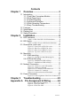
Chapter 1 Contents Overview........................................... 2 1.1 Introduction ......................................................... 2 1.1.1 Fast Fiber Converters Module ................... 2 1.1.2 Dual Power Input ....................................... 2 1.1.3 Flexible Mounting ...................................... 2 1.1.4 Advanced Protection ................................. 2 1.1.5 Wide Operating Temperature .................... 2 1.1.6 Easy Troubleshooting.............................
EKI-2741F-SX-LX User Manual viii
CHAPTER Overview Sections include: z Introduction z Features z Specifications z Packing List z Safety Precaution 1 Chapter1
Chapter 1 Overview 1.1 Introduction The EKI-2741 is designed to convert Gigabit Ethernet networks to Gigabit fiber networks by transparently converting Ethernet signals to optic signals. The advantages of fiber optics are wide bandwidth, EMI immunity and long-distance transmission capability. Therefore, EKI-2741 is an ideal solution for “fiber to building” applications at central offices or local sites. EKI-2741 supports MDI/MDIX auto detection, so you don’t need to use crossover wires.
1.
1.3 Specification Communications IEEE 802.3, 802.3ab, 802.3u, 802.3x, 802.
Environment Operating Temperature -10 ~ 60 ℃ (14~140℉) Wide temp. model: -40 ~ 75 ℃ (-40 ~ 167℉) -40 ~ 85 ℃(-40 ~ 185℉) 5 ~ 95% (non-condensing) 0 ~ 95% (non-condensing) Storage Temperature Operating Humidity Storage Humidity Certifications UL, 60950-1, CAN/CSA-C22.2 No.60950 U.S.A.
1.4 Packing List • • • • • • 1 x EKI-2741F or EKI-2741SX or EKI-2741LX Industrial Ethernet Switch 1 x eAutomation Industrial Communication CD-ROM with software, and User manual 2 x Wall Mounting Bracket and Screws 1 x DIN-rail Mounting Bracket and Screws 1 x EKI-2741F/SX/LX Startup Manual 1 x DC Jack Cable φ2.0/150mm 1.5 Safety Precaution Attention IF DC voltage is supplied by an external circuit, please use a protection device on the power supply input.
CHAPTER Installation Sections include: z LED Indicators z Dimensions z Mounting z Network Connection z Power Connection 7 Chapter2
Chapter 2 Installation In this chapter, you will be given an overview of the EKI-2741F/SX/LX hardware installation procedures. 2.1 LED Indicators There are few LEDs display the power status and network status located on the front panel of EKI-2741F/SX/LX, each of them has its own specific meaning as the table below. Table 2.
2.2 DIP-Switch The DIP-Switch is used to configure operation mode for LFP (Link Fault PassThrough) and operation mode for UTP/Fiber port. The default value of DIP-switch is OFF. Table 2.
2.3 Dimensions (units: mm) Figure 2.
Figure 2.
Figure 2.
The terminal block of power & relay is located on the top side. Please refer to page 16 for pin assignment. Figure 2.
2.4 Mounting The EKI-2741F/SX/LX support two mounting methods: DIN-rail & Wall. 2.4.1 Wall mounting EKI-2741F/SX/LX can be wall-mounted by using the included mounting kit. Then, hang on the EKI-2741F/SX/LX to the nails on the wall. First, use the screws included in the package to combine the EKI-2741F/SX/LX and metal mounting kit. And then you can install the device firmly via the components, please see Figure 2.5 as below. Figure 2.
2.4.2 DIN-rail Mounting You can also mount EKI-2741F/SX/LX on a standard DIN-rail by below steps. The DIN-rail kit is screwed on the industrial switch when out of factory. If the DIN-rail kit is not screwed on the industrial switch, please screw the DIN-rail kit on the switch first. First, hang the EKI-2741F/SX/LX to the DIN-rail with angle of inclination. See figure 2.6. Figure 2.
Then, let the device down straight to slide over the rail smoothly. See Figure 2.7 Figure 2.
2.5 Network Connection • Twisted-pair segment can use unshielded twisted pair (UTP) or shielded twisted pair (STP) cabling. The cable between the link partner (switch, hub, workstation, etc.) and the converter, must be less than 100 meters (328 ft.) long and comply with the IEEE 802.3ab 1000Base-T standard for Category 5e or above. • Fiber segment using single-mode connector type must use 9/125 µm single-mode fiber cable. You can connect two devices in the distance of 10 km.
Second, insert the fiber cable of LC connector into the transceiver. Figure 2.10: LC connector to the transceiver To remove the LC connector from the transceiver, please follow the steps shown below: First, press the upper side of the LC connector from the transceiver and pull it out to release. Figure 2.
Second, push down the metal loop and pull the transceiver out by the plastic part. Figure 2.
2.6 Power Connection The EKI-2741F/SX/LX support dual +12 ~ 48 VDC power inputs and power-fail relay output. Figure 2.13: Pin Assignment of the Power Connector You can connect an alarm indicator, buzzer or other signaling equipment through the relay output. The relay opens if power input 1 or 2 fails ( “Open” means if you connect relay output with an LED, the light would be off).
CHAPTER Troubleshooting 21 Chapter2
Chapter 3 Troubleshooting 1. Power Input Verify that is using the right power cord/adapter (+12~48 VDC), please don’t use the power adaptor with DC output voltage higher than 48V, or it will burn this converter down. 2. Cable Select the proper UTP/Fiber cable to construct your network. The single-mode converter must use single-mode fiber cable. Please check that you are using the right cable. 3. DIP Switch Check the configuration DIP-switch.
APPENDIX Pin Assignment & Wiring 23 Chapter2
Appendix A Pin Assignment & Wiring It is suggested to adopt ELA/TIA as the wiring of the RJ-45. Figure A.1: RJ-45 Pin Assignment Figure A.2: EIA/TIA-568B Figure A.