EKI-6311G IEEE 802.
Contents Chapter 1. Introduction ............................................................................. 4 1.1 1.2 1.3 1.4 1.5 Introducing the EKI-6311G ......................................................................... 4 Product Features ........................................................................................... 4 Package Contents .......................................................................................... 4 System Requirements ...................................
4.4.4 ACL for Wi-Fi 4 .............................................................................. 36 SNMP ........................................................................................................... 37 4.5.1 Agent Settings.................................................................................. 37 4.6 EXIT............................................................................................................. 37 4.5 Chapter 5. Specifications ..................................
Chapter 1. 1.1 Introduction Introducing the EKI-6311G The EKI-6311G is fully interoperable with IEEE 802.11b/g compliant Wireless Last-mile product. The EKI-6311G operates in AP mode or remote bridge mode, and connects to EKI-6311G AP/CB to construct point-to-point as well as point-to-multipoint topologies, for maximum flexibility in configuring building-to-building networks and WISP functions. 1.
1.4 System Requirements Installation of the EKI-6311G Outdoor Wireless Access Point/Client Bridge requires the following: 1. A Windows-based PC/AT compatible computer(PC system requirement: better than PIII 800 or other 100% compatible equipment , OS:windows 2000/XP ) or Ethernet data device with an available RJ-45 Ethernet port to run the configuration program or with TCP/IP connection to the Ethernet network. 2. A 10/100Base-T Ethernet RJ-45 Ethernet cable is connected to Ethernet network. 3.
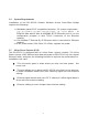
Chapter 2. Installation and Basic Configuration This chapter describes the procedures of installing the EKI-6311G. 2.1 Before You Start After unpacking the system, make sure the following items are present and in good condition. Refer to below pictures for product image. 1. EKI-6311G Outdoor Wireless Access Point/Client Bridge unit 2. 100~240VAC, 50~60Hz AC to 48V/0.375A DC switching adapter 3. Inline Power Injector (PoE) 48VDC, 0.375A 4. Grounding wire 1.8m 5. User manual CD-disc 6.
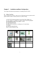
2.2 Locate the EKI-6311G and Inline Power Injector Ports ► Interface on the EKI-6311G Unit ¾ Ethernet Port 1 : for connecting the RJ-45 CAT-5 Ethernet cable. ► Interface on the Inline Power Injector ¾ Data Input Port 2 : for connecting cross-over Ethernet Cable to PC or straight Ethernet cable to Hub Switch Router . ¾ DC Input Port 3 : power adapter 48V, 0.375A DC input. ¾ Power & Data Output Port 4 : for connecting the RJ-45 CAT-5 Ethernet Cable. ¾ Grounding Port 5 : for connecting grounding wire.
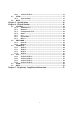
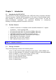
► Mount EKI-6311G on A Wall/Mast The EKI-6311G can be mounted on the wall, you can use the Wall Mount kit to mount the EKI-6311G as shown in Figure 2-2. Figure 2-2 You can also mount the EKI-6311G to the mast as shown in Figure 2-3.
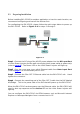
2.3 Preparing Installation Before installing EKI-6311G for outdoor application or hard-to-reach location, we recommend configuring and test all the devices first. For configuring the EKI-6311G, please follow the quick steps below to power up the EKI-6311G. Refer to Figure 2-4 for steps 1 through 5. Figure 2-4 Step1 : Connect the DC plug of the AC/DC power adapter into the DC Input Port of Inline Power Injector and the wall-mount plug into a power outlet or power strip (refer to page 6).
2.4 2.4.1 Basic Configuration Basic Configuration Steps This section describes a two-step SYSTEM configuration procedure to setup EKI-6311G. Step1 : Modify the factory-default parameters on the “/Network/Network/”, and click APPLY to save the changes. web page Step2 : Modify the factory-default parameters on the web page “/WIRELESS/Wi-Fi 1”, and click APPLY to save the changes, than click “/SYSTEM/Reboot/”Reboot to take effect on the previous configuration changes. 2.4.
Figure 2-5 Step3 : Enter “admin” in the Username and Password fields, and click LOGIN to enter the web configuration user interface screen as shown below. Figure 2-6 ► Web Configuration Structure The web configuration user interface shown above in Figure 2-6 is grouped into a tree structure, and contains the following settings or information.
● ● ● Log System Time Reboot ▽ NETWORK ● Network ● HotSpot ▽ WIRELESS ● Wi-fi 1 ● Wi-fi 2 ● Wi-fi 3 ● Wi-fi 4 ▽ ACL ● ● ● ● ACL ACL ACL ACL for for for for Wi-fi Wi-fi Wi-fi Wi-fi 1 2 3 4 ▽ SNMP ● Agent Settings ▽ EXIT Move through the tree by clicking on an icon to expand or collapse the tree. The nodes on the tree represent web pages that allow viewing and modifying the parameters.
2.4.3 Set Operating Mode, IP Address, Subnet Mask, Default Route IP, DNS Server IP of EKI-6311G ► LAN Settings These are the settings of the LAN (Local Area Network) interface for the Access Point. The Access Point's local network (LAN) settings are configured based on the IP Address and Subnet Mask assigned in this section. The IP address is also used to access this Web-based management interface. This option is available in the “/NETWORK/ NETWORK /” page as shown in Figure 2-7.
The IP address of the AP on the local area network. Assign any unused IP address in the range of IP addresses available for the LAN. For example, 192.168.1.1. ► Subnet Mask The subnet mask of the local area network. ► Gateway The IP address of the router on the local area network. ► DNS Server This entry is optional. Enter a DNS Server for the local network.
2.4.4 Set Wireless SSID for Wireless Interface ► Wireless Network Name (Also called the SSID) When you are browsing for available wireless networks, this is the name that will appear in the list (unless Visibility Status is set to Invisible, see below). This name is also referred to as the SSID. For security purposes, it is highly recommended to change from the pre-configured network name.
2.4.5 Set Wireless Encryption for Wireless Interface The EKI-6311G supports 64-bit and 128-bit WEP encryption. For 64-bit WEP encryption, an encryption key is 10 hexadecimal characters (0-9 and A-F) or 5 ASCII characters. For 128-bit WEP encryption, an encryption key is 26 hexadecimal characters or 13 ASCII characters. Modify the WEP encryption parameters on the web page “/WIRELESS/Wi-Fi 1 SECURITY ”. Choice “WEP” Enter 1~15 characters into the WEP Key field, than click Apply ,“/SYSTEM/Reboot ”Reboot.
2.4.6 Change Supervisor Account & Password Enter the SYSTEM > Administrator page. Figure 2-10 below shows the SYSTEM / Administrator page. Figure 2-10 ► ADMIN PASSWORD Key in current password in the SYSTEM / Administrator / Password Setting Current Password field. Change the ADMIN PASSWORD’s password in the SYSTEM / Administrator Password Setting Password and Re-type Password fields, and click APPLY ,than,“/SYSTEM/Reboot ”Reboot.
2.4.7 ► Upgrade the Firmware Update the Firmware Enter the SYSTEM > FIRMWARE page as shown in Figure 2-11 to upgrade EKI-6311G. Here, user must select which file you want to upgrade it (Program image), then click APPLY button to start the upgrade process. Hint: When choose “using web” for updating, choose the image file for updating directly. Do not unzip the image file. i.e. Image file name: ”Advantech-V 2.0.4.tgz” Hint: It takes about 10 min, to complete the restart process.
2.4.8 ► DHCP server DHCP server Enter the Network > Network page as shown in Figure 2-12 to Enable the DHCP server. Here, user can set IP Pool Address range, lease time and Local domain name. Then click APPLY button to set the parameter and click Reboot button for saving parameter. Figure 2-12 Caution The Part 15 radio device operates on a non-interference basis with other devices operating at this frequency when using integrated antennas.
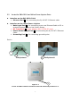
Chapter 3. Network Topologies This chapter describes several common types of installations implemented by using the EKI-6311G’s line of Outdoor Wireless System. This is by no means intended to be an exhaustive list of all possible configurations, but rather shows examples of some of the more common implementations. The EKI-6311G CB can be configured to function as a Wireless Client Router or Bridge to a central access point like the EKI-6311G AP see Figure 3-1 below.
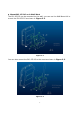
3.1 Wireless Client Bridge-to-Central Wireless Bridge Figure 3-2 Refer to Figure 3-2 for the following setup. Note: The EKI-6311G AP is the Central Wireless Bridge and EKI-6311G CB is the Wireless Client Bridge Step 1 Set the EKI-6311G AP to perform a bridge (bridge IP address: 192.168.1.1). Step 2 Set Wireless parameters on the AP to: Channel (1) and SSID (wireless) Step 3Set the EKI-6311G CB to function in the bridge mode (bridge IP address: 192.168.1.241).
Chapter 4. 4.1 4.1.1 All function on Device SYSTEM Administrator Administrator Settings Use this menu to restrict management access based on a specific password. The default password comes with the installation guide. Please change this password as soon as possible, and store it in a safe place. Passwords can contain from 3-12 alphanumeric characters,and are case sensitive. Figure 4-1 Administrator Time-out The amount of time of inactivity allowed before the user proceeds next action.
4.1.2 Firmware Figure 4-2 Firmware Update – WEB You can use WEB to upgrade the firmware. The "firmware information" displays current firmware version and firmware date. On the managed computer, specify the folder in which the firmware file resides. Click APPLY to complete your change. At the end of the upgrade, the Wireless device may not respond to commands for as long as ten minute. This is normal behavior and do not turn off the Wireless device during the time.
respond to commands for as long as ten minute. This is normal behavior and do not turn off the Wireless device during the time. Firmware Update - FTP You can use FTP to upgrade the firmware. The "firmware information" displays current firmware version and firmware date. Enter FTP Server IP , Type the correct firmware file path and file name on the File field. Keyin the current FTP Username and Password . Click on APPLY to complete your change.
4.1.3 Configuration Tools Figure 4-3 Restore Factory Defaults - Reset the device's configuration settings to the factory default values. Check the "Restore Factory Default Configuration" radio button then click on APPLY button. Backup settings/Restore settings - Check the "Backup settings/Restore settings" radio button then click on APPLY button. Backup Settings - Press the "Backup Settings" button to save the settings of this device to a file named "config.bin" on your PC.
4.1.4 Status Figure 4-4 You can use the Status screen to see the connection status for the LAN and Wireless LAN interfaces. It also displays system up time and firmware version. The following items are included in this screen: WAN INFORMATION - Displays IP settings of WAN port, including IP Address, Subnet Mask, and Gateway. LAN INFORMATION - Displays IP settings of LAN port, including IP Address and Subnet Mask.
4.1.5 Log Figure 4-5 The Access Point automatically logs (records) events of possible interest in its internal memory. If there is not enough internal memory for all events, logs of older events are deleted, but logs of the latest events are retained. The Logs option allows you to view the Access Point logs.
4.1.6 System Time Figure 4-6 The Time Configuration option allows you to configure, update, and maintain the correct time on device's internal system clock. From this section you can set the time zone that you are in and set the Time Server. Time Configuration- Set the Date and Time Manually. If you do not have the NTP Server option in effect, you can either manually set the time for your Access Point here.
4.1.7 Reboot Figure 4-7 Reset Wireless device. In the event that the Wireless device stops responding correctly or in some way stops functioning, you can perform a reboot. Your existing settings will not be changed. To perform the reset, click on the Reboot button. You will be asked to confirm your decision.
4.2 NETWORK 4.2.1 Network 4.2.1.1 Operating Mode-Access Point IP Assignment DHCP Choose "DHCP (Dynamic)" if your router supports DHCP and you want the router to assign an IP address to the AP. In this case, you do not need to fill in the following fields. Figure 4-8 Manual Choose "Manual" if your router does not support DHCP or if for any other reason you need to assign a fixed address to the AP. In this case, you must also configure the following fields.
Subnet Mask The subnet mask of the local area network. Gateway The IP address of the router on the local area network. DNS Server DNS (Domain Name System), Penetrates the DNS system, We may look up its IP by machine domain name, Also may instead look up its domain name by machine IP This entry is optional. Enter a DNS Server for the local network.
PPPoE Choose "PPPoE" if your Internet support PPPoE Server .You need keyin Username and Password to login PPPoE Server. Figure 4-10 4.2.1.2 Operating Mode-Access Point 4.2.1.3 Operating Mode-CB+AP 4.2.1.4 Operating Mode-AP Router 4.2.1.5 Operating Mode-Access Point 4.2.1.6 Operating Mode-CB+AP Router 4.2.1.
4.2.2 HotSpot(Captive Portal) HotSpot: Enable/Disable captive portal function. Note, the device will become router mode and ALL SSID in Access Point role after HotSpot enabled. Domain: Set domain name for hotspot. Primary Radius: Set primary radius server for hotspot user authentication. Secondary Radius: Set backup radius server for hotspot user authentication. NAS ID: Set device's NAS ID in RADIUS frames. Called Station Name: Set device's station name in RADIUS frames.
4.
4.3.1 Wi-Fi 1 Wireless Settings Radio Status: Enable/Disable SSID. Wireless Role: This SSID will act as Station or Access Point. Note: only first SSID can act as station. Radio Mode: Set 11g, 11b or 11b+g mode. Radio Channel: Select radio channel or use auto. Peer Node Distance: Set distance between this device and it's adjacent. SSID: Set (extended) service set ID, a.k.a. netwrok name.
4.4 ACL You can set the access control releated setting here Figure 4-13 4.4.1 ACL for Wi-Fi 1 Wireless MAC ACL Wireless MAC ACL Status: Enable/Disable ACL by MAC address. Add New MAC Address: Add a new MAC address to MAC table and in active status. MAC Table: Active, this MAC will be checked. Inactive, this MAC will ignore for checking. Remove, remove this MAC from MAC table. 4.4.2 ACL for Wi-Fi 2 4.4.3 ACL for Wi-Fi 3 4.4.
4.5 SNMP You can set the SNMP Community and SNMP Trap setting here 4.5.1 Agent Settings SNMP Agent provides a simple protection. Access to the SNMP device is controlled through community names. The community name can be thought of as a password. If you don't have the correct community name, you can't retrieve any data (get) or make any change (set). Multiple SNMP managers may be organized in a specified community. You can change your SNMP community settings on this screen.
Chapter 5. Specifications The EKI-6311G Outdoor Wireless Access Point/Multi-Client Bridge/ WDS (wireless distribution system) operates seamlessly in the 2.4 GHz frequency supporting the IEEE 802.11b/802.11g wireless standards. It's the best way to add wireless capability to your existing wired network, or to add bandwidth to your existing wireless installation.
Features z z z z z z z z High Speed Data Rate Up to 54Mbps Power-over-Ethernet (IEEE802.3af Compliant) Output Power up to 19dBm IEEE 802.11b/g Compliant WEP/WPA/WPA2/ IEEE 802.1x Authenticator support Dust tight and Watertight and Weatherproof (IP65) Wide temperature range and robust mechanical design Multi-SSID (up to 4 SSID) support Technical Specifications Data Rates 1, 2, 5.5, 6, 9, 11, 12, 18, 24, 36, 48, 54 Mbps Standards IEEE802.11b/g, IEEE802.1x, IEEE802.3, IEEE802.3u Compatibility IEEE 802.
Networking Topology Ad-Hoc, Infrastructure Operation Mode Access Point / CB+AP / AP Router / CB+AP Router / HotSpot AP / VLAN AP / VLAN CB+AP Interface One 10/100Mbps RJ-45 LAN Port , RS-232 Console Security IEEE802.
Chapter 6. 6.1 Default Settings SYSTEM 6.1.1 Administrator Parameter Description Hostname Default Value Advantech.lan Current Password Password Re-type Password 30 Idle Time Out Enable 0.0.0.0 IP address 6.1.2 Firmware Parameter Description Default Value Using TFTP Using FTP Using WEB 6.1.3 Configuration Tools Parameter Description Restore Factory Default Configuration Backup Settings / Restore Settings 6.1.
6.1.5 Log 6.1.6 System Time Parameter Description Default Value Setting by Synchronize with an Internet Time Server Year / Month / Day 07/8/20 Hour : Minute : Second 02:26:06 Hours from UTC +8 Server IP pool.ntp.org NTP Server for Reference pool.ntp.org or 129.132.2.21 Time Update for 0/0/0 Every 6.1.
6.2 NETWORK 6.2.1 Network Parameter Description Default Value Operating Access Point IP Assignment Manual IP Address 192.168.1.1 Subnet Mask 255.255.255.0 Gateway 0.0.0.0 DNS Server 0.0.0.0 Link Integrity Disable PPPoE Username PPPoE Password 6.2.2 Hotspot Parameter Description HotSpot Status Default Value Disable Domain Primary Radius 0.0.0.0 1812 Secondary Radius 0.0.0.
6.3 WIRELESS 6.3.1 Wi-Fi 1 Parameter Description Default Value Country TAIWAN Radio Status Enable Wireless Role Access Point Radio Mode 802.11b+g Radio Channel Channel 1, 2412MHz Peer Node Distance 100 meters SSID Advantech/1 Transmission Power 17dBm Frag.
6.3.2 Wi-Fi 2 Parameter Description Default Value Country TAIWAN Radio Status Disable Wireless Role Access Point Radio Mode 802.11b+g Radio Channel Channel 1, 2412MHz Peer Node Distance 100 meters SSID Advantech/2 Transmission Power 17dBm Frag.
6.3.3 Wi-Fi 3 Parameter Description Default Value Country TAIWAN Radio Status Disable Wireless Role Access Point Radio Mode 802.11b+g Radio Channel Channel 1, 2412MHz Peer Node Distance 100 meters SSID Advantech/3 Transmission Power 17dBm Frag.
6.3.4 Wi-Fi 4 Parameter Description Default Value Country TAIWAN Radio Status Disable Wireless Role Access Point Radio Mode 802.11b+g Radio Channel Channel 1, 2412MHz Peer Node Distance 100 meters SSID Advantech/4 Transmission Power 17dBm Frag.
6.4 ACL 6.4.1 ACL for Wi-Fi Parameter Description Default Value Wireless MAC ACL Status Disable Add New MAC Address 00:00:00:00:00:00 Wireless On/Off Scheduling Status Disabled Scheduling on Sunday 0 24 Scheduling on Monday 0 24 Scheduling on Tuesday 0 24 Scheduling on Wednesday 0 24 Scheduling on Thursday 0 24 Scheduling on Friday 0 24 Scheduling on Saturday 0 24 6.4.
6.4.3 ACL for Wi-Fi 3 Parameter Description Default Value Wireless MAC ACL Status Disable Add New MAC Address 00:00:00:00:00:00 Wireless On/Off Scheduling Status Disabled Scheduling on Sunday 0 24 Scheduling on Monday 0 24 Scheduling on Tuesday 0 24 Scheduling on Wednesday 0 24 Scheduling on Thursday 0 24 Scheduling on Friday 0 24 Scheduling on Saturday 0 24 6.4.
6.5 SNMP Parameter Description Default Value Agent Status Enable System Location System Contact System Name Advantech System Description Advantech Wireless AP/CB Read Only Community public Read Write Community Private 6.
Chapter 7. Regulatory Compliance Information Federal Communication Commission Interference Statement This equipment has been tested and found to comply with the limits for a Class B digital device, pursuant to Part 15 of the FCC Rules. These limits are designed to provide reasonable protection against harmful interference in a residential installation.
Antenna type Antenna Gain Omni 5dBi 52