EKI-6321AG EKI-6322AG EKI-6323AG 802.
Copyright The documentation and the software included with this product are copyrighted 2010 by Advantech Co., Ltd. All rights are reserved. Advantech Co., Ltd. reserves the right to make improvements in the products described in this manual at any time without notice. No part of this manual may be reproduced, copied, translated or transmitted in any form or by any means without the prior written permission of Advantech Co., Ltd. Information provided in this manual is intended to be accurate and reliable.
Product Warranty (2 years) Advantech warrants to you, the original purchaser, that each of its products will be free from defects in materials and workmanship for two years from the date of purchase. This warranty does not apply to any products which have been repaired or altered by persons other than repair personnel authorized by Advantech, or which have been subject to misuse, abuse, accident or improper installation.
Federal Communication Commission Interference Statement This equipment has been tested and found to comply with the limits for a Class B digital device, pursuant to Part 15 of the FCC Rules. These limits are designed to provide reasonable protection against harmful interference in a residential installation. This equipment generates uses and can radiate radio frequency energy and, if not installed and used in accordance with the instructions, may cause harmful interference to radio communications.
Technical Support and Assistance Step 1. Visit the Advantech web site at www.advantech.com/support where you can find the latest information about the product. Step 2. Contact your distributor, sales representative, or Advantech’s customer service center for technical support if you need additional assistance.
Safety Precaution - Static Electricity Follow these simple precautions to protect yourself from harm and the products from damage. 1. To avoid electrical shock, always disconnect the power from your PC chassis before you work on it. Don't touch any components on the CPU card or other cards while the PC is on. 2. Disconnect power before making any configuration changes. The sudden rush of power as you connect a jumper or install a card may damage sensitive electronic components.
Chapter 1. Overview 1.1. Features EKI-6321AG, EKI-6322AG and EKI-6323AG are perfectly ideal wireless solutions for outdoor long range deployment, ultra fast roaming and reliable and robust wireless infrastructure. All of them provide 5GHz/ 2.4GHz dual band radio functionality with clean and highly reliable wireless point-to-point (PtP) or point-to-multipoint (PtMP) performance for distant locations.
- Harsh Outdoor Environments Sustainable o Certified IP67 sturdy water-tight housing o Wide operating temperature range from -35~70 ℃ - System Management : o Firmware upgrade through TFTP, FTP o Interface status display o SNMP v1/v2 - Simple Installation and Deployment : o Software Alignment / Deployment Tools 8
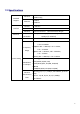
1.2. Specifications Standard Support Interface Ethernet Wireless IEEE802.11a IEEE802.11b/g Ethernet IEEE802.3 IEEE802.3u Console RS 232 Port Ethernet 1×10/100 Base-T RJ-45 Wireless Antenna Connector: Max. Bandwidth Standard Reversed Female N-type Full Duplex: 100Mbps (for 100BASETX), 10Mbps (for 10BaseT) AP / AP Client / Bridge / Router USA: 2.412 – 2.462GHz, Frequency Range 5.725~ 5.850GHz Europe: 2.400 – 2.483GHz, 5.15~ 5.35GHz, 5.47 ~ 5.725GHz Japan: 2.400 – 2.483GHz, 4.90 – 5.
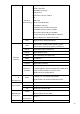
IEEE 802.11a/b/g Mode Selection Enable / Hide SSID MAC Address Filtering Fixed Channel DHCP Client / Server, Fixed IP NAT Wireless SNMP v1v2 Other Setting 802.1q VLAN-Multi SSID MAC Address Filtering Bandwidth Control of Wireless Client MS NetBIOS IP Filter Enable / Disable 802.
Spec. Humidity 0% ~ 95% non-condensing Notes on 802.11a operation frequency: Some countries have allocated certain 802.11a frequency bands strictly for indoor use only. Do make sure the operation frequency follows your local regulation. Some areas may have penalty when operating outdoor AP in a wrong frequency band. Advantech takes no responsibility for any penalty or loss caused by using illegal frequency band for Advantech EKI-6321AG/ EKI-6322AG/ EKI-6323AG. Chapter 2.
5. 6. Mounting Kit & Screw Set Quick Installation Guide. 7. Dual Band Omni Directional Antenna for 2400 - 2500 / 5150 - 5875 MHz (2.5dBi@2400MHz ; 5dBi@5800MHz) 8. CD: User Manual Please contact your local distributor/reseller if any of the above items is missing. 1.4. Hardware Description 3.2.1. The Outdoor AP Unit The outdoor AP unit has one antenna port on top, one data/power port and one console port at the bottom. The antenna ports are N-type female connectors.
The port on right side of the photo is power/signal connector port. It is an 8-pin female connector with M12 to RJ45 Ethernet Cable Converter waterproof. Connecting to the Power & Data Output Port of PoE by RJ-45 Ethernet cable. The port on right side of the photo is Console port (TBD). It is an 8-pin male connector with MIL-C-5015 IP67 waterproof. Connecting to the PC for initial configuration and diagnostics & troubleshooting. 2.
Connections Antenna Connector: 1 × Reversed Female N-type Connect to Antenna base by Male to Male N-type CFD 400 RF Cable Special Consol Port Connect one end of the 2M MIL-C-5015 IP67 RS-232 console port cable to this port; connect the other end to a Serial Port on a computer that is running a terminal emulation program; connect the another end to a Serial Port on a notebook or PDA that is running Alignment / Deployment tools program for technicians to analysis RF equipments.
3. Mounting Kit The mounting kit is used to provide a good support for the outdoor unit and the flat panel antenna. Please follow the installation procedure to mount the outdoor unit and the flat panel antenna. The contents of the mounting kit are shown below. A. Wall Mounting Kit B. Mast Mounting Kit 4. Grounding wire The grounding wire is used to provide the grounding path for the outdoor unit to minimize the impact of lightening and surge.
1.5. Outdoor Installation Before installation, please read and follow the precautions to the installation: 1. Users MUST use a proper and well-installed surge protector in the outdoor installation. Otherwise, lightening surge may damage the devices. Lightning DAMAGE IS NOT COVERED UNDER WARRNTY. 2. Users MUST use the PoE Injector shipped in the box. 3. Users MUST power off the device first before connecting the external antenna to it.
Step 4 Run Ethernet cable from Data Input Port(at the front of the PoE)to the Ethernet Port on the PC or notebook.
Step 5 Connect M12 to RJ45 Ethernet Cable adaptor into MIL-C-5015 Ethernet port at the bottom of the access point.
The installer may adjust the Ethernet cable length according to the requirement of installation in field. Special Notice for Waterproof Installation Most of the problems for outdoor models are from the connector connections that loosen over time due to vibration or other forces, even allowing moisture to penetrate the connector and seriously affecting the data and radio signal transmit. The following recommendation is used for all outdoor installation to be waterproofed.
Chapter 4. Basic Configurations Login Access the system web user’s interface by insert the device IP address in URL of the web browser. The factory default IP address is 192.168.1.1. Login ID and password is required before access the system web user’s interface. The default user’s ID is admin and password is password. After insert the correct user’s ID and password, user will be able to enter the system web user’s interface.
The following sections outline each selection item. 4.
4.1.1 System General Setup 1.1.1 System General Setup – Basic Setup Device Name & Description For identifying a particular outdoor access point. System Operation Mode AP can operate in either bridge mode or router mode. Note that when the AP is configured to operate in bridge mode, all four interfaces operate as bridge. When it is operating in route mode, all interfaces will belong to different IP subnet. NetBIOS Filter When enabled, each client cannot be seen on MicroSoft Network Neighborhood.
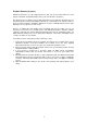
DC-MESH DC-MESH is developed to improve wireless backbone connection to enhance better performance in overall throughput rate of the deployment. DC-MESH is a passive wireless backbone link failover methodology. "Wireless Station" interface will automatically switch the wireless backbone connection to another "Access Point" node (which has same ESSID ,ISP ID and SUB ID configuration).
dynamic backbone route on wireless backbone passively when failure node occur. Because DC-MESH is a passive mechanism, link in wireless backbone can be more efficient than normal MESH. DC MESH feature description There are two DC-MESH mode devices in DC-MESH deployment: Gateway Node "Gateway Node" will be the first device of a Daisy Chain topology, a "Gateway Node" connects wireless network and wire network.
There is a set of connection code for "Normal Node" to decide reconnecting access point in DC-MESH topology: ISP ID "ISP ID" is a specific 32bits digitized code for one wireless network service provider. When "Normal Node" is switching to the other Daisy Chain link, "Normal Node" will match the "ISP ID" of the new Access Point before connection is created. SUB ID "ISP ID" is an assistant code of "ISP ID". Usage of "SUB ID" is same as "ISP ID".
"DC-MESH Route Rule" provided the information for "Normal Node" to decide new wireless backbone route: Max Hops "Max Hops" setting limits the maximum node numbers in a Daisy Chain link. "Normal Node" will chose the less hops to reconnect when route is switching.
Max RSSI Each device in Daisy Chain will have a "RSSI score" to add up the total RSSI in Daisy Chain route to the Gateway Node. When 2 available Daisy Chain paths have same number of hops the "Normal Node" will chose the less RSSI score to reconnect when route is switching. In the example above, node C will chose node A2 to rebuild the Daisy Chain connection because the Total RSSI Score Path A is more efficient than Path B, even the RSSI between C and B2 is better than A2.
1.1.3 System General Setup – System Data/Time Set System Date & Set System Time Set the date and time NTP Setup When any NTP server is available in network, user can enable the NTP and system will automatically synchronize system time with NTP server. DNS Setup In order to enable NTP service, DNS setting is required for resolving domain name into IP address. Current Clock Indicating the current clock of the AP (set by user).
1.2 Interface Configuration Interface Configuration is for configure the Ethernet interface and the multi wireless interfaces in system. All the physical settings of interfaces are configured here. Each interface can be individually enable/disable. When system is configured as a bridge, the IP address of system is set in the Bridge interface. Depends on the system, DHCP server and gateway can also be set in this page.
The following settings can be configured for the wireless interfaces: In Bridge Mode In Router Mode Individual IP subnet belongs to specific interface will available in setting.
Operation Mode Each interface can be set as an access point (AP) or a wireless station (also called AP client (AC)). When the interface is an AP, it accepts connection requests from wireless clients, such as wireless internet cards in PC or WiFi phones. When the interface is a wireless station, it looks for the AP with the same ESSID to connect. It will not accept any connection request from other wireless clients. ESSID/MESSID Assign ESSID to the interface for connection identification.
station problem does not exit from the perspective of the AP. RTS Threshold can be set between 1 and 2312 bytes. Frag Threshold Setting the packet size to activate fragmentation. Frag Threshold can be set between 1 and 2312 bytes. Link Rate Set the data link rate for system. When it is set to AUTO, system will use the maximum possible link rate to transmit the data. MAX RF Distance System can adjust the TTL of packets according to the given distance to improve the communication quality.
1.4 Routing Configuration (Configuration only available when Router operation mode) System also provides static routing table for network administrators to edit the necessary static route rule.
4.2 Advanced Setting Under advanced settings, you will be able to configure the following: System Password Wireless Performance DHCP Configuration NAT Configuration SNMP configuration Wireless Security Setting 2.1 System Password The factory default web user interface password is “password”. Please do change it into another to secure the system login.
2.2 Wireless Performance In order to serve higher quality of wireless hotspot, system provides Bandwidth Control and QoS setting for administrator to divide difference bandwidth service for various client connections. 2.2.1 Bandwidth Control Downstream and upstream data rates for subscriber or the client devices connecting to AP can be defined here. There are two bandwidth limit types in system.
For specific client connections, system provides a table for network administrator to limit bandwidth of each individual client by MAC address. Once these client MAC addresses are set in the table, the general bandwidth limit rule will not apply to the connection of devices with these MAC address. Only the specified bandwidth limit rule applied. The table will support up to 64 MAC address in table.
2.2.2 QoS Setting DSCP Differentiated Services Code Point (DSCP) is a 6-bit field in the header of IP packets for packet classification purposes. DSCP replaces the outdated IP precedence, a 3-bit field in the Type of Service byte of the IP header originally used to classify and prioritize types of traffic. Protocol Protocol base QoS mechanism differentiate packets by TCP/UDP service port to assign packets in different priority level.
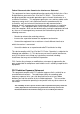
2.3 DHCP Configuration The scope of DHCP client pool that corresponds to the selected interface and subnet are defined in this menu. Lease (D) is the duration that the DHCP server grants to the DHCP client permission to use a particular IP address. Lease (M) is the maximum lease time. Each Ethernet or wireless interface can be the gateway of its own subnet. Hence there can be three subnet domains in one AP in routing mode. This DHCP configuration is only available when SYSTEM is operating in router mode.
Bridge Mode Router Mode 39
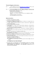
2.4 NAT Configuration Network Address Translation can be setup in four different ways: 1. Port forwarding NAT (Server sets) Server sets where internal IP addresses are mapped according to the TCP or UDP port are defined in this Port Forwarding NAT sub-menu.
2. Static NAT (One to One Mapping) In this menu, you will be able to map internal private IP address to a global WAN IP address. 3. Dynamic NAT (Many to Many Mapping) A range of internal IP address can be mapped to a range of global IP address.
4. Single Address NAT (PAT) A range of internal IP address can be mapped to a range of global IP address. The configuration is only available when system is operating in router mode. 2.5 SNMP configuration SNMP is configured here for simple network management. System supports all SNMP v1, v2 and v3. The private MIBs file can also be download from this page .
2.6 Wireless Security Setting Comprehensive security settings are available on system in this menu. These include Hide ESSID, WEP Keys, 802.1x EAP-TLS, 802.1x EAP-MD5, WPA-PSK, WPA-EAP, MAC Address Filtering and RADIUS. Details of each type of security are in appendix. The security setting of each wireless interface is configured separately. Note the message at the bottom of SMT page for information on each selection items.
2.6.1 MAC Address Filtering System can control the client connection by accepting or blocking the traffic from devices of specific MAC addresses.
2.6.2 RADIUS RADIUS settings for 802.1x protocol authenticating with the remote RADIUS server for authenticating, authorization and accounting are set in this menu.
4.3 System Management 3.1 Configuration Management The configuration of system can be backed-up or restored by using TFTP here. In a daisy chained sequential configurations, it is recommended to backup all configurations before uploading/upgrading firmware. You may name your configuration file in any ways you like. The configuration of system can be reset to factory default by using this menu.
3.2 Security File Management For running EAP_TLS secure connection, network administrators may need to able to upload User Certificate, Root Certificate and RSA Key file to the system. In this menu, system allowed administrators to upload these Certificate files through TFTP server to the access point. Please refer Annotations for more on wireless security. 3.
Download the new firmware from Internet to the management PC and click Browse to select the file. Please do not shutdown the system during the upgrading process to prevent unexpected system failure. System will automatically reboot and perform image backup after the upgrade. New firmware will take effect after system reboot. Please refer to application note on firmware upgrade for step by step upgrading process.
3.4 System reboot Reboot system from web UI without disconnecting power cable or changing any connection. Certain configurations require system reboot to take place, such as configuration restore. 4.4 System Monitoring In System Monitoring sector, it provides system monitoring for device. The following sections introduce each menu : 4.1 Interface Link Status Real-time link statuses of all interfaces are shown in the menu. - System Up Time Display how long WLD–600A1 has been operating since last boot-up.
Transmit power of wireless interface set in SMT-12. - Data Link Rate Real-time data transmission rate. When Data Link Rate in “Interface Configuration” is set, it displays here. Otherwise, when it is set as AUTO in “Interface Configuration”, Data Link Rate here indicates the maximum transmission rate available, and can be used as an indication of link quality. The maximum link rate according to 802.11a/g is 54Mbps. It Only available when the interface is set as an AC.
4.2 Wireless Survey In Wireless Survey, system provides a signal scan function to detect any available wireless signal around the AP. It will help AP installer to clarify the environment. 4.2.1 Client List All the connecting clients’ MAC address will be display in Client List, including signal and data rate.
4.3 System log System provide a setting of remote system log server, device will upload all system log to remote log server to provide network administrator to monitor the health of device. System provides seven system log levels (Level1=DEBUG Level2=EMERGENCY Level3=ALERT Level4=CRITICAL Level5=ERROR Level8=WARNING Level7=NOTICE Level8=INFO) to indicate the level of attention needed for each log.
4.4 System Information System Information summarizes all the configuration and hardware information of the device.
Appendix Antenna concepts and Installations I.1. Basic Terminology - Transmit Power The RF power coming out of the antenna port of a transmitter. It excludes the signal loss of the coaxial cable or the gain of the antenna, and is measured in dBm, Watts or milli-Watts - Receiver Sensitivity The weakest RF signal level (usually in negative dBm) that a radio needs to receive in order to demodulate and decode a data packet without errors.
As a signal spreads out from a radiating source, the energy spreads out over a larger surface area. As this occurs, the strength of that signal gets weaker. FSL specifies how much the signal has weakened over a given distance, and it is measured in dB. I.2. RF Path Loss and Transmission Distance Calculation System Gain (dBm) is the is the total gain of radio without antenna/cable System Gain = Tx power – Rx Sensitivity FSL = Tx Power + Tx Antenna Gain + Rx Antenna Gain– Rx Sensitivity = 32.
II. Wireless Security Concept II.1. Security for 802.11 Network Security for 802.11 networks can be simplified into two main components: authentication and encryption. WEP (Wired Equivalent Privacy) is part of the system security of 802.11, and its goals are to provide confidentiality and data integrity, and to protect access to the network infrastructure by rejecting all non-WEP packets. With 802.
Bit - A binary digit. Browser - An application program that provides a way to look at and interact with all the information on the World Wide Web. CSMA/CA (Carrier Sense Multiple Access/Collision Avoidance) - A method of data transfer that is used to prevent data collisions. CTS (Clear To Send) - A signal sent by a wireless device, signifying that it is ready to receive data.
Hardware - The physical aspect of computers, telecommunications, and other information technology devices. IEEE (The Institute of Electrical and Electronics Engineers) - An independent institute that develops networking standards. Infrastructure - A wireless network that is bridged to a wired network via an access point. IP (Internet Protocol) - A protocol used to send data over a network. IP Address - The address used to identify a computer or device on a network.
communications, and other services. SNMP (Simple Network Management Protocol) - A widely used network monitoring and control protocol. Software - Instructions for the computer. A series of instructions that performs a particular task is called a "program". Spread Spectrum - Wideband radio frequency technique used for more reliable and secure data transmission. SSID (Service Set IDentifier) - Your wireless network's name.
Protocol) encryption, which can be used in conjunction with a RADIUS server.