
Computer Hardware User Manual


PCM-9587 User Manual 20
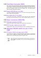
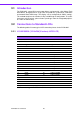
3.1 Introduction
The PCM-9587 system BIOS and custom drivers are located in a 512 Kbyte, Flash
ROM device, designated U6. A single Flash chip holds the system BIOS, VGA BIOS
and network Boot ROM image. The display can be configured via CMOS settings.
This method minimizes the number of chips and difficulty of configuration. To set dif-
ferent types of LCD panels, please choose “panel type” from the “integrated peripher-
als” menu in CMOS setup.
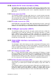
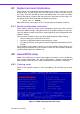
3.2 Connections to Standard LCDs
The following tables illustrate typical LCD connection pinouts for the PCM-9587.
3.2.1 LG LM150X06 (1024x768(16 colors) LVDS LCD)
* LCD connector type: HRS DF 19K-20P-1H or compatible
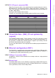
Table 3.1: Connections to LCD/ Flat Panel (CN8)
LCD Connector Flat Panel Connector
Unipac-UB104S01 DF-13 40P
Pin Signal Pin Signal
1VCC 1 3.3V
2VCC 2 3.3V
3 GND 3 GND
4 GND 4 GND
5 RxIN0- 7 LVDS_YAM0R
6 RxIN0+ 9 LVDS_YAP0R
7GND 11GND
8 RxIN1- 13 LVDS_YAM1R
9 RxIN1+ 15 LVDS_YAP1R
10 GND 17 GND
11 RxIN2- 19 LVDS_YAM2R
12 RxIN2+ 21 LVDS_YAP2R
13 GND 23 GND
14 CKIN- 25 LVDS-CLKAMR
15 CKIN+ 27 LVDS-CLKAPR
16 GND 29 GND
17 NC
18 NC
19 GND 33 GND
20 GND 34 GND