IPC-623 Series 20-slot 19" Rackmount Industrial PC Chassis User's Manual
Copyright Notice This document is copyrighted, April 1999, by Advantech Co., Ltd. All rights are reserved. Advantech Co., Ltd. reserves the right to make improvements to the products described in this manual at any time without notice. No part of this manual may be reproduced, copied, translated or transmitted in any form or by any means without the prior written permission of Advantech Co., Ltd. Information provided in this manual is intended to be accurate and reliable. However, Advantech Co., Ltd.
Contents Chapter 1 General Information .................................................. 1 1.1 Introduction .............................................................................................................. 1 1.2 Specifications .......................................................................................................... 1 General ..........................................................................................................................................................
2.10 Temperature Sensors ............................................................................................ 23 2.11 Filters ..................................................................................................................... 24 2.12 CPU Cards and Add-on Cards .............................................................................. 24 2.13 Hold-down Clamp ..................................................................................................
Chapter 1 General Information 1.1 Introduction The IPC-623 is a 4U 19" rackmount chassis that is ideal for CTI applications, as well as industrial automation systems. The IPC-623 can hold either a single IPC system or multi-systems, and can be configured with a 300 W redundant power supply or a 400 W single power supply. A 20-slot PCI/ISA backplane fits easily, as well as a wide variety of multi-segment PCI/ISA or ISA backplanes.
Environmental Specifications • Operating temperature: 0 ~ 45° C (32 ~ 113° F) • Relative humidity: 10 ~ 95% @ 40° C, non-condensing • Shock resistance: 30 G acceleration, peak to peak, 11 ms (non-operating) 10 G acceleration peak to peak, 11 ms acceleration peak to peak (operating) • Vibration: 5 ~ 500 Hz, 0.5 G sine wave, and 5 ~ 500 Hz, 1 G (rms.) random • Safety: CE compliant, C-UL approved 1.
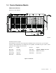
1.4 Passive Backplane Models PCA-6120: 20 ISA slots Dimensions: 420 x 200 mm Unit: mm Termination Resistor Signals The termination resistors provide an impedance mismatch at the end of the bus to prevent signal reflections. This mismatch has to be balanced by the capability of the CPU and option cards to electrically drive the load imposed by the resistor.
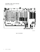
PCA-6120P4: 15 ISA / 4 PCI / 1 CPU slots Dimensions: 420 x 260 mm Unit: mm Figure 1-2: PCA-6120P4 4 IPC-623 User's Manual
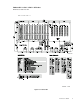
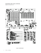
PCA-6119P7: 11 ISA / 7 PCI / 1 CPU slots Dimensions: 260 x 417 mm Unit: mm Figure 1-3: PCA-6119P7 IPC-623 User's Manual 5
PCA-6119P10: 8 ISA / 10 PCI / 1 CPU slots Dimensions: 260 x 417 mm Unit: mm Figure 1-4: PCA-6119P10 6 IPC-623 User's Manual
PCA-6119P17: 1 ISA / 17 PCI / 1 CPU slots Dimensions: 260 x 417 mm Unit: mm Figure 1-5: PCA-6119P17 IPC-623 User's Manual 7
PCA-6120D: 10 ISA slots x 2 Dimensions: 420 x 200 mm Unit: mm Termination Resistor Signals The termination resistors provide an impedance mismatch at the end of the bus to prevent signal reflections. This mismatch has to be balanced by the capability of the CPU and option cards to electrically drive the load imposed by the resistor.
PCA-6120DP4: 5 ISA / 4 PCI / 1 CPU slots x 2 Dimensions: 420 x 200 mm Unit: mm Figure 1-7: PCA-6120DP4 IPC-623 User's Manual 9
PCA-6118DP7: 5 ISA slots x 4 Dimensions: 260 x 417 mm Unit: mm Figure 1-8: PCA-6118DP7 10 IPC-623 User's Manual
PCA6120Q: 5 ISA slots x 4 Dimensions: 420 x 200 mm Unit: mm Figure 1-9: PCA-6120Q IPC-623 User's Manual 11
PCA-6116QP2: 1 ISA / 2 PCI / 1 CPU slots x 4 Dimensions: 260 x 417 mm Unit: mm Figure 1-10: PCA-6116QP2 12 IPC-623 User's Manual
1.5 Power Supply 300 watt redundant power supply Output rating: 300 W maximum Input voltage: 90/180 ~ 132/264 VAC @ 47 ~ 63 Hz Output voltage: +5 V @ 30 A, +12 V @ 12 A, -5 V @ 0.5 A, -12 V @ 1 A Min. load: +5 V @2 A, +12 V @ 1 A MTBF: 100 K hours Safety: UL/CSA/TUV/CE EMI: FCC part 15 class B, CISPR 22 class B, VCCI class 2 400 watt single power supply Output rating: 400 W maximum Input voltage: 100/200 ~ 130/260 VAC @ 47 ~ 63 Hz Output voltage: +5 V @ 40 A, +12 V @ 20 A, -5 V @ 0.5 A, -12 V @ 1 A Min.
1.
1.
Chapter 2 System Setup WARNING: Before starting the installation process, make sure you disconnect all power from the chassis. Do this by turning off the power switch and unplugging the power cord from the power outlet. If you are not sure what to do, let an experienced technician handle it. 2.1 Attaching the Handles The handles for the front panel are in the accessory box. To install the handles, simpy secure them to the front panel with the screws provided. 2.
2.3 Chassis Front and Rear Sections The IPC-623 comes in two sections: the front section and the rear section. Each of these sections has its own top cover. The front section includes: 1. Standard drive bay. 2. Three cooling fans. 3. Front chassis door. 4. Control panel. 5. Power supply (two power supply modules for the Power Redundant Supply Model; one power supply module for the Single Power Supply Model). 6. Additional drive bay (for the Single Power Supply Model only). The rear section includes: 1.
2.5 Four Models of the IPC-623 Advantech supplies four IPC-623 models. 2.5.1 The redundant power supply model In this configuration, the power supply is installed in the front section of the chassis. The 300 W redundant power supply comes in two modules, which are located at the left side of the front section. Figure 2-3-a Figure 2-3-b Both modules are hot-swappable and are accessible from the front. Please refer to figures 2-3-a and 2-3-b.
WARNING: Do not remove the power supply module if the front chassis door is not opened completely. Removing the power supply module in such a way might result in damage of your chassis. See figure 2-6. Figure 2-6: Do not do this! Replacing the redundant power supply module: 1. Make sure that the power supply module is the same rating as the one currently installed. 2. Open the front chassis door as wide as you can. See figures 2-4 and 2-5. 3. Slide the power supply module inward until it locks into place.
Installing an HDD into the drive bay: 1. Undo the four screws of the drive bay. 2. Align the hard drive with its proper position. 3. Fix the screws into the screw holes on the sides of the drive bay. 4. Connect the disk drive power and signal cables. 2.5.3 The 14-slot system model Figure 2-6-c Figure 2-6-d This model features a 14-slot backplane and a power supply module fitted at the rear section of the chassis. The front section has two standard drive bays, which allows installation of up to six 5.
This model allows an ATX motherboard with ATX power supply alongside, both of which are fitted at the rear section. Refer to figure 2-6-e. The front section is equipped with two standard bays, which enables installation of up to six 5.25" drives (CD-ROM, removable drive), two 3.5" floppy drives, and two internal 3.5" hard drives. See figure 2-6-f. For installing the drives in the standard drive bay, refer to section 2.4. 2.
2.7 Front Panel Switches The front panel switches are used for system power, system reset and alarm reset. Power On/Off Switch Used for switching the system power on or off. System Reset Switch Reinitializes the system. This switch is similar to the hardware reset button. Alarm Reset Switch For suppressing or stopping an audible alarm. Whenever a fault in the system occurs (e.g. fan failure, overtemperature, improper backplane voltage), an audible alarm is activated.
2.10 Temperature Sensors There are two temperature sensors inside the chassis. They are located at the rear section, attached to the left and right upper corner of the chassis backplate. Refer to figure 2-10. When the temperature rises, the sensors send a signal to the alarm board, and a continuous alarm is sounded. To stop the alarm, press the alarm reset switch at the front panel.
2.11 Filters There are four filtered ventilation holes, two on each side of the chassis. In addition, the fan filter is protected with a metal bracket. Replacing the fan filters: 1. Loosen the two screws that hold the metal bracket in place. 2. Remove the metal bracket. 3. Remove the filter, which you should either rinse with water or dispose of properly. 4. Use a new filter to replace the old one, or put the clean filter back. Make sure the filter is dry. 5.
Appendix A Jumper and Connector Settings A.1 Alarm Board Jumper Settings J1, J2, J3: MB and B/P Selection Function B/P version Jumper Settings J1, J2: 2-3 closed; J3: open (Default) MB version J1, J2: 1-2 closed; J3: closed J4: +3.