
User manual


MIO-5251 User Manual 8
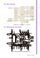
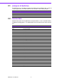
2.1 Jumpers & Switches
The MIO-5251 has a number of jumpers that allow you to configure your system to
suit your application. The table below lists the functions of the various jumpers.
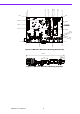
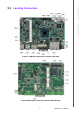
2.2 Connectors
Onboard connectors link the MIO-5251 to external devices such as hard disk drives,
a keyboard, or floppy drives. The table below lists the function of each of the connec-
tors.
Table 2.1: Jumpers & Switches
J2 Auto Power On
J5 LCD Power
SW2 Clear CMOS
Table 2.2: Connectors
Label Function
CN1 12V Power Input
CN4 SD Card
CN6 SODIMM
CN7 Power Switch
CN9 Reset
CN10 GPIO
CN11 VGA
CN12 HDMI (Optional DP)
CN13 SATA Power
CN14 SATA
CN15 Mini PCIe
CN16 mSATA
CN17 SIM Holder
CN18 External USB2.0
CN19 External USB3.0+USB2.0
CN20 COM1/2: RS-232
CN21 COM3/4: RS-232/422/485
CN24 GbE
CN27 Audio
CN29 MIOe
CN30 Inverter Power
CN31 LVDS
CN32 eDP
CN33
SMBus/I
2
C
CN34 Internal USB2.0
FAN1 System Fan