PCA-6190 LGA775 Pentium® 4/Celeron® D Processor Card with VGA/Dual Gigabit LAN/HISA/ DVI (800 MHz FSB) User’s Manual
Copyright Notice This document is copyrighted, 2005, by Advantech Co., Ltd. All rights are reserved. Advantech Co., Ltd. reserves the right to make improvements to the products described in this manual at any time without notice. No part of this manual may be reproduced, copied, translated or transmitted in any form or by any means without the prior written permission of Advantech Co., Ltd. Information provided in this manual is intended to be accurate and reliable. However, Advantech Co., Ltd.
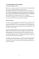
1.0.1 A Message to the Customer Advantech customer services Each and every Advantech product is built to the most exacting specifications to ensure reliable performance in the harsh and demanding conditions typical of industrial environments. Whether your new Advantech equipment is destined for the laboratory or the factory floor, you can be assured that your product will provide the reliability and ease of operation for which the name Advantech has come to be known.
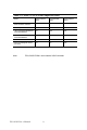
Table 1.1: Table 1.1: PCA-6190 Comparison Table Model PCA-6190VG00A1 PCA-6190G200A1 PCA-6190G2D0A1 VGA: Intel 915 GV integrated VGA controller onboard yes yes yes USB 2.
Table 1.2: PCA-6190 DDR memory compatibility table Brand Size Speed Type ECC Part Number Advantech PN Memory Apacer 1 GB DDR2 533 DDR2 N 78.01066. 330 NA HYB18T5 12 800AF37 FSS35249 0434 1 GB DDR2 533 DDR2 N 78.01066.
1.0.1 Product warranty Advantech warrants to you, the original purchaser, that each of its products will be free from defects in materials and workmanship for two years from the date of purchase. This warranty does not apply to any products which have been repaired or altered by persons other than repair personnel authorized by Advantech, or which have been subject to misuse, abuse, accident or improper installation.
1.0.
Important Safety Information SAFETY INSTRUCTIONS This device complies with the requirements in part 15 of the FCC rules: Operation is subject to the following two conditions: 1. This device may not cause harmful interference, and 2. This device must accept any interference received, including interference that may cause undesired operation This equipment has been tested and found to comply with the limits for a Class A digital device, pursuant to Part 15 of the FCC Rules.
Contents Chapter 1 Hardware Configuration .................................2 1.1 1.2 1.3 Introduction ....................................................................... 2 Features ............................................................................. 3 Specifications .................................................................... 4 1.3.1 1.3.2 1.3.3 1.3.4 1.3.5 1.3.6 1.3.7 1.4 System............................................................................. 4 Memory...................
2.8 2.9 2.10 2.11 2.12 2.13 Ethernet Connector (CN24) ............................................ 21 Serial Ports (COM1: CN9/CN91; COM2: CN10 ) ......... 22 PS/2 Keyboard/Mouse Connector (CN11)...................... 22 External Keyboard Connector (CN12)............................ 23 CPU Fan Connector (CN68) ........................................... 23 Front Panel Connectors (CN16, 17, 18, 19, 21&29)....... 24 2.13.1 2.13.2 2.13.3 2.13.4 2.13.5 2.13.6 2.14 2.15 2.16 2.17 2.18 2.19 2.20 2.21 2.
3.4.8 3.4.9 3.4.10 3.4.11 3.4.12 3.4.13 3.4.14 3.4.15 3.4.16 3.4.17 3.4.18 3.5 Advanced Chipset Features............................................. 38 3.5.1 3.5.2 3.5.3 3.5.4 3.5.5 3.5.6 3.5.7 3.5.8 3.5.9 3.5.10 3.5.11 3.5.12 3.5.13 3.5.14 3.5.15 3.6 Boot Other Device ........................................................ 36 Swap Floppy Drive ....................................................... 36 Boot Up Floppy Seek.................................................... 36 Boot Up NumLock Status...
3.6.14 GPIO Function.............................................................. 44 Figure 3.8:Super I/O Device......................................... 44 3.6.15 KBC Input Clock .......................................................... 44 3.6.16 Onboard FDC Controller .............................................. 44 3.6.17 Onboard Serial Port 1 ................................................... 44 3.6.18 Onboard Serial Port 2 ................................................... 45 3.6.
3.9.4 3.9.5 3.9.6 3.9.7 3.9.8 3.10 Current CPU Temperature ............................................ 50 CPU FAN Speed........................................................... 50 System FAN Speed....................................................... 50 VCORE and Other Voltages......................................... 50 Shutdown Temperature................................................. 50 Frequency / Voltage Control ........................................... 50 Figure 3.
Appendix C Pin Assignments ............................................98 C.1 IDE Hard Drive Connector (CN1) .................................. 98 C.2 Floppy Drive Connector (CN3)....................................... 99 C.3 Parallel Port Connector (CN4) ...................................... 100 C.4 USB Connector (CN6, CN63, CN66, CN67)................ 101 C.5 VGA Connector (CN7) ................................................. 101 C.6 VCN1 DVI connector......................................
C.22 GPIO Pin Header (SMD pitch=2.0mm) (CN93)........... 111 C.23 System I/O Ports............................................................ 111 C.24 DMA Channel Assignments.......................................... 112 C.25 Interrupt Assignments ................................................... 112 C.26 1st MB Memory Map.................................................... 113 C.27 PCI Bus Map ................................................................. 113 Table C.
PCA-6190 User’s Manual xvi
CHAPTER 1 General Information 1
Chapter 1 Hardware Configuration 1.1 Introduction The PCA-6190 is designed with the Intel 915GV chipset and ICH6 (I/O controller) to support 800 MHz Front side Bus, Intel Pentium 4/Celeron D processor, high speed/high capacity dual channel DDRII 400/533 memory, and high performance I/O functions such as dual Gigabit Ethernet ports, Serial/Parallel ATA ports, and PCI-Express host interface for LAN. In compliance with PICMG 1.
1.2 Features 1. Supports 4 Serial-ATA devices 2. Supports Dual Channel DDRII 400/533 SDRAM up to 4GB 3. Features a thermal protection circuit which will enable the processor to automatically shut down when the cooling system fails. 4. Supports DVI interface (optional) 5. Provides a 14-pin General Purpose I/O interface as the port80 function used in detecting hardware bugs or as the programmable 8-bit I/O. 6. Supports 10/100/1000Base-T Ethernet 7. 8 USB 2.0 ports 8.
1.3 Specifications 1.3.1 System • CPU: Intel LGA 775 Celeron D up to 3.06GHz, Pentium 4 up to 3.8 GHz, FSB 533/800 MHz. Advantech also certifies several high-performance CPU coolers as optional parts for customers who use highspeed CPUs in 2U chassis or high temperature environments.
• ISA bus: Supports ISA without DMA. PCI-to-ISA bridge: ITE IT8888 • AC-97 Audio: PCA-6190 can provide audio function with the optional audio extension module PCA-AUDIO-00A1 • USB port: Supports up to eight USB 2.0 ports with the two USB 2.0 cable kits included, and supports transmission rates up to 480 Mbps; available through two 4-USB port cable kits, P/N: 1700000719 1.3.4 VGA interface • Controller: Chipset integrated VGA controller • Display memory: Dynamically shared system memory up to 128 MB.
1.4 Jumpers and Connectors Connectors on the PCA-6190 single board computer link it to external devices such as hard disk drives and a keyboard. In addition, the board has a number of jumpers used to configure your system for your application. The tables below list the function of each of the board jumpers and connectors. Later sections in this chapter give instructions on setting jumpers. Chapter 2 gives instructions for connecting external devices to your single board computer. Table 1.
Table 1.
Notice: The 4-pin ATX 12V power connector "ATX1" must be connected to the power supply to provide adequate power to the CPU card. Otherwise, the system may become unstable.
CN19 CN17 CN16 ATX1 B CN68 CN21CN18 CN29 9 8 7 6 5 CN93 DDRII 4 DDRII 3 DDRII 2 DDRII 1 4 3 2 1 VCN1 CN67 CN65 CN91 CN9 CN10 CN12 CN6 CN63 CN66 CN4 CN24 CN20 J2 CN64 CN7 CN13 J1 CN22 CN30 CN43 CN11 CN1 SA0 SA1 CN3 SA2 SA3 SA3 1.5 Board Layout: Jumper and Connector Locations Figure 1.
1.6 PCA-6190 Block Diagram 533/800 MHz FSB Intel Pentium 4 LGA 775 Processor DDR II 400/533 Channel A CRT VG A Intel 915GV GMCH CH7307C 1 ATA 100 ports DMA 33/66/100 4 SATA ports 150MB/s 8 USB Ports USB 2.0/1.
1.7 Safety Precautions Warning! Always completely disconnect the power cord from your chassis whenever you work with the hardware. Do not make connections while the power is on. Sensitive electronic components can be damaged by sudden power surges. Only experienced electronics personnel should open the PC chassis. Caution! Always ground yourself to remove any static charge before touching the single board computer. Modern electronic devices are very sensitive to static electric charges.
1.8 Jumper Settings This section provides instructions on how to configure your single board computer by setting the jumpers. It also includes the single board computer's default settings and your options for each jumper. 1.8.1 How to set jumpers You can configure your single board computer to match the needs of your application by setting the jumpers. A jumper is a metal bridge that closes an electrical circuit.
1.8.3 Watchdog timer output (J2) The PCA-6190 contains a watchdog timer that will reset the CPU or send a signal to IRQ11 in the event the CPU stops processing. This feature means the PCA-6190 will recover from a software failure or an EMI problem. The J2 jumper settings control the outcome of what the computer will do in the event the watchdog timer is tripped. Table 1.
Note: System resources such as PCI require physical memory address locations that reduce available memory addresses above 3GB. This may result in less than 4GB of memory being available to the operating system and applications. 1.9.1 CPU FSB and memory speed The PCA-6190 can accept DDRII SDRAM memory chips without parity. Also note: The PCA-6190 accepts DDRII 400MHz SDRAM and DDRII 533MHz SDRAM, depending on the CPU front side bus frequency (FSB).
1.11 Processor Installation The CPU on the board must have a fan or heat sink attached, to prevent overheating. Warning: Without a fan or heat sink, the CPU will over-heat and cause damage to both the CPU and the single board computer. To install a CPU, first turn off your system and remove its cover. Locate the processor LGA775. 1. The CPU has a plastic cap on it to protect the contact from damage. Before you install the CPU, always cover it to protect the socket pin.
PCA-6190 User’s Manual 16
CHAPTER 2 Connecting Peripherals 17 Chapter 2
Chapter 2 Connecting Peripherals 2.1 Introduction You can access most of the connectors from the top of the board while it is installed in the chassis. If you have a number of cards installed or have a packed chassis, you may need to partially remove the card to make all the connections. 2.2 1st (CN1) IDE Connectors You can attach up to two IDE (Integrated Drive Electronics) drives to the PCA-6190’s built-in controller. The primary (CN1) connector can accommodate two drives.
2.3 Floppy Drive Connector (CN3) You can attach up to two floppy disk drives to the PCA-6190's on board controller. You can use 3.5" (720 KB, 1.44 MB) drives. The single board computer comes with a 34-pin daisy-chain drive connector cable. On one end of the cable is a 34-pin flat-cable connector. On the other end are two sets of 34-pin flat-cable connector (usually used for 3.5" drives). The set on the end (after the twist in the cable) connects to the A: floppy drive.
The parallel port is designated as LPT1, and can be disabled or changed to LPT2 or LPT3 in the system BIOS setup. To install the bracket, find an empty slot in your chassis. Unscrew the plate that covers the end of the slot. Screw in the bracket in place of the plate. Next, attach the flat-cable connector to CN4 on the CPU card. Wire 1 of the cable is red or blue, and the other wires are gray. Make sure that wire 1 corresponds to pin 1 of CN4. Pin 1 is on the upper right side of CN4. 2.
The PCA-6190 includes a VGA interface that can drive conventional CRT displays. CN7 is a standard 15-pin D-SUB connector commonly used for VGA. Pin assignments for CRT connector CN7 are detailed in Appendix B. 2.7 DVI Connector VCN1 (optional) The PCA-6190 provides an optional DVI interface that supports DVI display. The user can choose 26-pin to 20-pin DVI cable (p/n: 1700000821) for providing DVI connector. Pin assignments for DVI connector VCN1 are detailed in Appendix B. 2.
2.9 Serial Ports (COM1: CN9/CN91; COM2: CN10 ) The PCA-6190 offers two serial ports, CN9/CN91 as COM1 (CN9 for PCA-6190G2; CN91 for PCA-6190VG) and CN10 as COM2. These ports can connect to serial devices, such as a mouse or a printer, or to a communications network. The IRQ and address ranges for both ports are fixed. However, if you want to disable the port or change these parameters later, you can do this in the system BIOS setup. Different devices implement the RS-232 standard in different ways.
2.11 External Keyboard Connector (CN12) In addition to the PS/2 mouse/keyboard connector on the PCA-6190's rear plate, there is also an extra onboard external keyboard connector. This gives system integrators greater flexibility in designing their systems. 2.12 CPU Fan Connector (CN68) The PCA-6190 provides 4 pin CPU fan connector.
2.13 Front Panel Connectors (CN16, 17, 18, 19, 21&29) There are several external switches to monitor and control the PCA-6190 2.13.1 Power LED (CN16) CN16 is a 5-pin connector for the power on LED. Refer to Appendix B for detailed information on the pin assignments. If a PS/2 or ATX power supply is used, the system's power LED status will be as indicated below: Table 2.
2.13.3 Reset (CN18) Many computer cases offer the convenience of a reset button. Connect the wire for the reset button. 1 2.13.4 HDD LED (CN19) You can connect an LED to connector CN19 to indicate when the HDD is active. 1 2.13.5 ATX soft power switch (CN21) If your computer case is equipped with an ATX power supply, you should connect the power on/off button on your computer case to CN21. This connection enables you to turn your computer on and off. 2.13.
2.14 ATX Feature Connector (CN20) Connect to the CN1 on the Advantech backplane to enable the ATX function, 5V stand-by. 2.15 AC-97 Audio Interface (CN43) The PCA-6190 provides AC-97 audio through PCA-AUDIO-00A1 module from Advantech. 2.
In addition to the one EIDE interfaces (up to two devices), the PCA-6190 provides four high performance serial ATA interfaces (up to 150MB/s) which eases cabling to hard drives with thin and long cables. 2.17 Connecting to SNMP-1000 Remote Manager Use the 6-pin to 8-pin cable to connect the single board computer to SNMP-1000. This cable comes with the SNMP-1000. CN21 CN18 CN19 CN29 CN19 PIN 1 PIN 1 SNMP-1000 CPU Card 2.
2.19 SCSI Daughterboard Extension Connector (CN30) The PCA-6190 is equipped with an Adaptec AIC-7899 single-chip PCIto-SCSI host adapter which provides a dual channel Ultra 160 multitasking interface between your computer’s PCI bus and SCSI devices (disk drives, CD-ROM drives, scanners, tape backups, removable media drives, etc.). Ultra 160 is a new generation of SCSI technology that expands SCSI performance from 80 MBytes/s to 160 MBytes/s.
2.21 Front Panel LAN Indicator Connector (CN65) If you want to observe your LAN operating status through the front LED of system, you can connect the front LAN LED to the CN65 connector to indicate the LAN operating status. The indication of the front LAN LED is same as the indication of the RJ45 on the rear plate. 2.22 GPIO Pin Header (CN93) PCA-6190 particularly has a 14-pin General Purpose I/O interface as the port80 function used in detecting hardware bugs or as the programmable 8-bit I/O.
PCA-6190 User’s Manual 30
CHAPTER 3 Award BIOS Setup 31 Chapter 3
Chapter 3 Award BIOS Setup 3.1 Introduction Award’s BIOS ROM has a built-in setup program that allows users to modify the basic system configuration. This type of information is stored in battery backed-up memory (CMOS RAM) so that it retains the setup information when the power is turned off. 3.1.1 CMOS RAM Auto-backup and Restore The CMOS RAM is powered by an onboard button cell battery. When you finish BIOS setup, the data in CMOS RAM will be automatically backed up to Flash ROM.
3.2 Entering Setup Turn on the computer and press to enter the BIOS setup. Figure 3.1: Award BIOS Setup initial screen 3.3 Standard CMOS Setup 3.3.1 Date The date format is , , , . 3.3.2 Time The times format in , based on the 24-hour military time clock. 3.3.3 IDE channel 0/1 Master/Slave 1. IDE HDD Auto-Detection: Press "Enter" to select this option for automatic device detection. 2. IDE Device Setup.
5. Cylinder Number of cylinders 6. Head: Number of heads 7. Precomp: Write precomp 8. Landing Zone: Landing zone 9. Sector: Number of sectors 3.3.4 Drive A / Drive B This category identifies the types of floppy disk drives installed in the system. The options are: None/360K, 5.25"/1.2M, 5.25"/720K, 3.5"/ 1.44M, 3.5"/2.88M, 3.5". 3.3.5 Halt On This category determines whether system start-up will halt or not when an error is detected during power up.
3.4 Advanced BIOS Features The “Advanced BIOS Features” screen appears when choosing the “Advanced BIOS Features” item from the “Initial Setup Screen” menu. It allows the user to configure the PCA-6190 according to his particular requirements. Below are some major items that are provided in the Advanced BIOS Features screen. A quick booting function is provided for your convenience. Simply enable the Quick Booting item to save yourself valuable time. Figure 3.3: Advanced BIOS features screen 3.4.
3.4.2 Hard Disk Boot Priority Set hard disk boot device priority. 3.4.3 Virus Warning Enable virus warning, the commands are "Enabled" or "Disabled". 3.4.4 CPU L1 & L2 Cache Enabling this feature speeds up memory access. The commands are “Enabled” or “Disabled.” 3.4.
3.4.13 Typematic Rate Setting The typematic rate is the rate key strokes repeat as determined by the keyboard controller. The commands are “Enabled” or “Disabled.” Enabling allows the typematic rate and delay to be selected. 3.4.14 Typematic Rate (Chars/Sec) BIOS accepts the following input values (characters/second) for typematic rate: 6, 8, 10, 12, 15, 20, 24, 30. 3.4.
3.5 Advanced Chipset Features By choosing the “Advanced Chipset Features” option from the “Initial Setup Screen” menu, the screen below will be displayed. This sample screen contains the manufacturer’s default values for the PCA-6190, as shown in Figure 3-4: Figure 3.4: Advanced chipset features screen Note: DRAM default timings have been carefully chosen and should ONLY be changed if data is being lost. Please first contact technical support. 3.5.
3.5.3 DRAM RAS# to CAS# Delay When the DRAM Timing selectable is set to [Manual], this field is adjustable. When DRAM is refreshed, the rows and columns are addressed separately. This setup item allows user to determine the timing of the transition from RAS (row address strobe) to CAS (column address strobe). The less the clock cycles are, the faster the DRAM speed is. Setting options: [2T] to [5T], [Auto]. 3.5.
3.5.10 PCI-Express Root Port Func PCI Express Port 1/2/3/4 The default setting is “Auto.” The choices are “Enabled,” “Disabled,” and “Auto.” PCI-E Compliancy Mode It allows user to select the PCI-E compliant mode. Setting options: [v1.0], [v1.0a]. 3.5.11 On-Chip Video Memory Size Use this field to select On-Chip Frame Buffer Size, Fixed Memory Size and DVMT Memory Size. Total Graphics Memory can be set as 64 MB, 128 MB or 224 MB. 3.5.
3.6 Integrated Peripherals Figure 3.5: Integrated peripherals Figure 3.6: On-Chip IDE Device 3.6.1 IDE HDD Block Mode If your IDE hard drive supports block mode select Enabled for automatic detection of the optimal number of block read/writes per sector the drive can support. 3.6.2 IDE DMA Transfer Access Use this field to enable or disable IDE DMA transfer access.
3.6.3 On-Chip IDE Device IDE Primary Master/Slave PIO/UDMA Mode (Auto). The channel has both a master and a slave, making four IDE devices possible. Because two IDE devices may have a different Mode timing (0, 1, 2, 3, 4), it is necessary for these to be independent. The default setting “Auto” will allow auto detection to ensure optimal performance. 3.6.4 SATA Mode The setting choices for the SATA Mode are IDE, RAID and AHCI Mode. Select [IDE] if you want to have SATA function as IDE.
Figure 3.7: Onboard Device 3.6.8 USB Controller Select Enabled if your system contains a Universal Serial Bus (USB) controller and you have USB peripherals. The choices: "Enabled," "Disabled." 3.6.9 USB 2.0 Controller This entry is to disable/enable the USB 2.0 controller only. The BIOS itself may/may not have high-speed USB support. If the BIOS has high speed USB support built in, the support will automatically turn on when a high speed device is attached. The choices are : "Enabled" or "Disabled." 3.6.
Note: PCA-6190VG-00A1 uses onboard LAN2 controller 3.6.14 GPIO Function Options are "Enabled" and "Disabled." Select Disabled if you don’t want to use GPIO function. . Figure 3.8: Super I/O Device 3.6.15 KBC Input Clock This BIOS feature allows you to adjust the keyboard interface clock for a better response or to fix a keyboard problem. It is recommended that you select the 16MHz option for a better keyboard response.
3.6.18 Onboard Serial Port 2 The settings are "3F8/IRQ4", "2F8/IRQ3", "3E8/IRQ4", "2E8/ IRQ3" and "Disabled" for the on-board serial connector. 3.6.19 UART Mode Select This item allows you to select UART mode. The choices: "IrDA", "ASKIR", "Normal". 3.6.20 RxD, TxD Active This item allows you to determine the active of RxD, TxD. The Choices: “Hi, Hi,” “Lo, Lo,” “Lo, Hi,” “Hi, Lo.” 3.6.21 IR Transmission Delay This item allows you to enable/disable IR transmission delay.
3.7 Power Management Setup The power management setup controls the single board computer's “green” features to save power. The following screen shows the manufacturer’s defaults. Figure 3.9: Power management setup screen (1) 3.7.1 Power Supply Type PCA-6190 can support both "ATX" and "AT" power supply. Customers can choose the PSU type through this selection. The choices are: "ATX","AT". While selecting "AT", the ACPI function will disable automatically. 3.7.
Min Saving Minimum power management., Suspend Mode = 1 hr., and HDD Power Down = 15 min. Max Saving Maximum power management., Suspend Mode = 1 min., and HDD Power Down = 1 min. User Defined (Default) Allows you to set each mode individually. When not disabled, each of the ranges are from 1 min. to 1 hr. except for HDD Power Down which ranges from 1 min. to 15 min, and disabled. 3.7.4 Video Off Method Use this to select the method to turn off the video.
3.7.13 PowerOn by Alarm The Choice : "Enabled", "Disabled". 3.7.14 Primary IDE 0 (1) and Secondary IDE 0 (1) When Enabled, the system will resume from suspend mode if Primary IDE 0 (1) or Secondary IDE 0 (1) is active. The choice: "Enabled", "Disabled". 3.7.15 FDD, COM, LPT PORT When Enabled, the system will resume from suspend mode if FDD, COM port, or LPT port is active. The choice: "Enabled", "Disabled". 3.7.16 PCI PIRQ [A-D]# When Enabled, the system will resume from suspend mode if interrupt occurs.
3.8.1 Reset Configuration Data Default is Disabled. Select Enable to reset Extended System Configuration Data (ESCD) if you have installed a new add-on, and system configuration has caused such a conflict that OS cannot boot. 3.8.2 Resources Controlled By The commands here are "Auto(ESCD)" or “Manual.” Choosing “Manual” requires you to choose resources from each following sub-menu. "Auto(ESCD)" automatically configures all of the boot and Plug and Play devices, but you must be using Windows 95 or above.
3.9.2 CPU Warning Temperature This item will prevent the CPU from overheating. The choices are: "Disabled,""60C/140F," "63C/145F," "66C/151F," "70C/158F," "75C/167F," "80C/176F," "85C/185F," "90C/194F," and "95C/205F." 3.9.3 Current System Temperature This shows you the current temperature of system. 3.9.4 Current CPU Temperature This shows you the current CPU temperature. 3.9.5 CPU FAN Speed This shows you the current CPU FAN operating speed. 3.9.
3.10.1 CPU Clock Ratio Key in a DEC number to set up the CPU Clock Ratio (Min=14; Max=17). This item only shows up in special situations. 3.10.2 Spread Spectrum This setting allows you to reduce the EMI by modulating the signals the CPU generates so that the spikes are reduced to flatter curves. It achieves this by varying the frequency slightly so that the signal does not use any particular frequency for more than a moment. The choices are: "Disabled," and “Enabled.” 3.
3.12 Save & Exit Setup If you select this and press , the values entered in the setup utilities will be recorded in the CMOS memory of the chipset. The microprocessor will check this every time you turn your system on and compare this to what it finds as it checks the system. This record is required for the system to operate. 3.13 Exit Without Saving Selecting this option and pressing lets you exit the setup program without recording any new values or changing old ones.
CHAPTER 4 Chipset Software Installation Utility 53 Chapter 4
Chapter 4 Chipset Software Install Utility 4.1 Before you begin To facilitate the installation of the enhanced display device drivers and utility software, you should read the instructions in this chapter carefully before you attempt installation. The device drivers for the PCA-6190 board are located on the software installation CD. The auto-run function of the driver CD will guide and link you to the utilities and device drivers under a Windows system.
• Identification of Intel® chipset components in the Device Manager. • Integrates superior video features. These include filtered sealing of 720 pixel DVD content, and MPEG-2 motion compensation for software DVD Note: This utility is used for the following versions of Windows system, and it has to be installed before installing all the other drivers: Windows 98SE Windows 2000 Windows Me Windows XP 4.3 Windows XP Driver Setup 1. Insert the driver CD into your system's CD-ROM drive.
2. Click "Next" when you see the following message. 3. Click "Yes" when you see the following message.
4. Click "Next" when you see the following message. 5. When the following message appears, click "Finish" to complete the installation and restart Windows.
PCA-6190 User’s Manual 58
CHAPTER 5 VGA Setup 59 Chapter 5
Chapter 5 VGA Setup 5.1 Introduction The Intel 915GV integrated graphics controller provides an analog display port and DVI interface through SDVO ports. You need to install the VGA driver to enable the function. The features include: • Intel Graphics Media Accelerator 900: Incorporating the latest Microsoft* DirectX*9 support capabilities, it allows software developers to create real-life environments and characters.
5.2 Windows XP Driver Setup Note: Before installing this driver, make sure the CSI utility has been installed in your system. See Chapter 4 for information on installing the CSI utility Insert the driver CD into your system's CD-ROM drive. In a few seconds, the software installation main menu appears, as shown in the following figure. The following installation procedure is for Windows XP. For other operating systems, please do a manual installation.
1. Please click on "Next" to continue the installation 2. You will see a welcome window. Please chick on "Yes" to continue the installation. .
3. Click "Finish" to complete the installation and restart the computer now or later.
PCA-6188 User’s Manual 64
CHAPTER 6 LAN Configuration 65 Chapter 6
Chapter 6 LAN Configuration 6.1 Introduction The PCA-6190 features single/dual Gigabit Ethernet network interface. With the Broadcom BCM5721 GbE controller designed-in, PCA-6190 implements the PCI Express host interface (PCI-E X1) in LAN connection with the maximum throughput of 2Gbps for heavy-duty industrial network application. 6.2 Features Integrated 10/100/100 BASE-T transceiver 1. 10/100/1000 BASE-T triple-speed MAC 2. High-speed RISC core with 24-KB cache 3. On-chip voltage regulation 4.
6.4 Win XP Driver Setup (Broadcom BCM5721) 1. Insert the driver CD into your system's CD-ROM drive. In a few seconds, the software installation main menu appears, as shown in the following figure. Under the "LAN Drivers" heading, click on the "Manual" to open file manager, then click "SETUP.EXE" to run the installation procedure. 2.
3. You will see the license agreement. Please click on "next" to continue the installation. 4. Click "Install" to continue.
5. Click "Finish" to complete the installation.
PCA-6190 User’s Manual 70
CHAPTER 7 USB 2.
Chapter 7 USB 2.0 Configuration 7.1 Introduction The PCA-6190 is designed with Intel ICH6 which supports both USB1.1 and USB 2.0 high-speed transmission. It remains compatible with today's USB device. High-speed USB 2.0 provides data transfer up to 480Mb/s which is 40 times faster than USB 1.1. It is ideal for today's speeddemanding I/O peripherals. 7.2 Features • Provides data transmission rate up to 480Mb/s • Offer 40X greater bandwidth than USB 1.
CHAPTER 8 Onboard Security Setup 73 Chapter 8
Chapter 8 Onboard Security Setup 8.1 Introduction The PCA-6190's hardware monitor is designed with Winbond W83627HF. Onboard security (OBS) functions monitor key hardware. They help you maintain your system's stability and durability. The PCA6190 can monitor 5 sets of system positive voltages, 2 sets of system negative voltages, CPU cooling fan speed, and CPU temperature. The positive system voltage sets which can be monitored include: • CPU core voltage: 1.3 V ~ 3.3 V, according to Intel specifications.
8.2 Windows XP Driver Setup 1. Insert the driver CD into your system's CD-ROM drive. In a few seconds, the software installation main menu appears, as shown in the following figure. Click on the "Install" button under the "OBS DRIVERS" heading. 2. Click "Next" when you see the following message.
3. Click "Next" when you see the following message. 4. Click "Next" when you see the following message.
5. Click "Finish" to complete the installation 6. Click "Finish" when you see the following message.
8.3 Using the OBS Hardware Doctor Utility After completing the setup, all the OBS functions are permanently enabled. When a monitored reading exceeds safe limits, a warning message will be displayed and an error beep tone will activate to attract your attention. OBS Hardware Doctor will show an icon on the right side of the bottom window bar. This icon is the "Terminate and Stay Resident" (TSR) icon.
79 Chapter 8
PCA-6190 User’s Manual 80
Appendix A Programming the Watchdog Timer 81 Appendix A
Appendix A Programming the watchdog A.1 Programming the Watchdog Timer The PCA-6190's watchdog timer can be used to monitor system software operation and take corrective action if the software fails to function after the programmed period. This section describes the operation of the watchdog timer and how to program it. A.1.1 Watchdog timer overview The watchdog timer is built into the super I/O controller W83627HF.
Unlock W83627H Select register of watchdog timer Enable the function of the watchdog timer Use the function of the watchdog timer Lock W83627HF 83 Appendix A
Watchdog Timer Registers Address of register (2E) Attribute Read/Write Value (2F) and description 87 (hex) ----- Write this address to I/O address port 2E (hex) twice to unlock theW83627HF 07 (hex) write Write 08 (hex) to select register of watchdog timer. 30 (hex) write Write 01 (hex) to enable the function of the watchdog timer. Disabled is set as default. F5 (hex) write Set seconds or minutes as units for the timer.
F7 (hex) read/write Bit 6: Write 1 to enable keyboard to reset the timer, 0 to disable.[default] Bit 5: Write 1 to generate a timeout signal immediately and automatically return to 0. [default=0] Bit 4: Read status of watchdog timer, 1 means timer is ""time out""." AA (hex) ----- Write this address to I/O port 2E (hex) to lock the watchdog timer.2 Table A.1: Watchdog timer registers A.1.4 Example Program 1. Enable watchdog timer and set 10 sec.
;----------------------------------------------------------Dec dx ; Set second as counting unit Mov al,0f5h Out dx,al Inc dx In al,dx And al,not 08h Out dx,al ;----------------------------------------------------------Dec dx ; Set timeout interval as 10 seconds and start counting Mov al,0f6h Out dx,al Inc dx Mov al,10 Out dx,al ;----------------------------------------------------------Dec dx ; lock W83627HF Mov al,0aah Out dx,al 2.
;----------------------------------------------------------Dec dx ; Enable the function of watchdog timer Mov al,30h Out dx,al Inc dx Mov al,01h Out dx,al ;----------------------------------------------------------Dec dx ; Set minute as counting unit Mov al,0f5h Out dx,al Inc dx In al,dx Or al,08h Out dx,al ;----------------------------------------------------------Dec dx ; Set timeout interval as 5 minutes and start counting Mov al,0f6h Out dx,al Inc dx Mov al,5 Out dx,al ;-------------------
Out dx,al ;----------------------------------------------------------Mov al,07h ; Select registers of watchdog timer Out dx,al Inc dx Mov al,08h Out dx,al ;----------------------------------------------------------Dec dx ; Enable the function of watchdog timer Mov al,30h Out dx,al Inc dx Mov al,01h Out dx,al ;----------------------------------------------------------Dec dx ; Enable watchdog timer to be reset by mouse Mov al,0f7h Out dx,al Inc dx In al,dx Or al,80h Out dx,al ;------------------
Out dx,al ;----------------------------------------------------------Mov al,07h ; Select registers of watchdog timer Out dx,al Inc dx Mov al,08h Out dx,al ;----------------------------------------------------------Dec dx ; Enable the function of watchdog timer Mov al,30h Out dx,al Inc dx Mov al,01h Out dx,al ;----------------------------------------------------------Dec dx ; Enable watchdog timer to be strobed reset by keyboard Mov al,0f7h Out dx,al Inc dx In al,dx Or al,40h Out dx,al ;-------
Out dx,al ;----------------------------------------------------------Mov al,07h ; Select registers of watchdog timer Out dx,al Inc dx Mov al,08h Out dx,al ;----------------------------------------------------------Dec dx ; Enable the function of watchdog timer Mov al,30h Out dx,al Inc dx Mov al,01h Out dx,al ;----------------------------------------------------------Dec dx ; Generate a time-out signal Mov al,0f7h Out dx,al Inc dx In al,dx ;Write 1 to bit 5 of F7 register Or al,20h Out dx,al ;
Appendix B Programming the GPIO 91 Appendix B
Appendix B Programming the GPIO B.
_M_END: ENDM ;-----------------------------------------------------------; Logic_Dev_Sel ;-----------------------------------------------------------Logic_Dev_Sel MACRO Log_Dev MOV DX,2Eh ; MOV AL,07h ; Point To Logical Device Number Reg.
.386 .DATA MSG_1 db 0ah,0dh,"GP10-13 Output/GP14-17 Input .....$ " MSG_2 db 0ah,0dh,"GP10-13 Input /GP14-17 Output .....$ " MSG_3 db "Test OK! $ ",0ah,0dh .
mov dx,2eh ;Logic Device 7 CR-F0(GPIO 10-17) mov al,0f0h ; out dx,al ;-Index (F0) mov dx,2fh ; mov al,0fh ; 1=GPI/0=GPO GPIO[7:4]=GPO out dx,al ;-Data(0F) GPIO[3:0]=GPI Print MSG_2 MTEST1 50h ;50h=0101b Print MSG_3 ;-----------------------------------------------------------MOV INT END AH,4CH 21H BEGIN END 95 Appendix B
PCA-6190 User’s Manual 96
Appendix C I/O Pin Assignments 97 Appendix C
Appendix C Pin Assignments C.1 IDE Hard Drive Connector (CN1) Table C.
C.2 Floppy Drive Connector (CN3) 33 31 3 1 34 32 4 2 Table C.
C.3 Parallel Port Connector (CN4) 13 12 2 1 26 25 15 14 Table C.
C.4 USB Connector (CN6, CN63, CN66, CN67) 1 2 3 4 5 6 7 8 9 10 Table C.4: USB1/USB2 connector (CN6) Pin USB1 Signal Pin 1 +5 V 6 2 UV7 3 UV+ 8 4 GND 9 5 Chassis GND 10 USB2 Signal +5 V UVUV+ GND N/CA C.5 VGA Connector (CN7) 5 1 10 6 15 11 Table C.
C.6 VCN1 DVI connector Table C.6: VCN5 DVI connector Pin Signal 1 #TMDS1_0 2 AGP_5V_TMDS2 3 TMDS1_0 4 GND 5 GND 6 TMDS1_CK 7 #TMDS1_1 8 GND 9 #TMDS1_1 10 DDC3_SCLOUT Pin 11 12 13 14 15 16 17 18 19 20 Signal GND DDC3_SDAOUT #TMDS1_2 #TMDS1_2 TMDS1_2 ATI_12C_DAT AGP_5V_TMDS2 ATI_12C_CLK CPIS_ENA_BL CPIS_VDD_VCL C.7 COM1/COM2 RS-232 Serial Port (CN9/CN91/CN10) Table C.
5 6 7 8 9 GND DSR RTS CTS RI C.8 Keyboard and Mouse Connnector (CN11) Table C.
C.9 External Keyboard Connector (CN68) Table C.9: External keyboard connector (CN12) Pin Signal 1 CLK 2 DATA 3 NC 4 GND 5 VCC C.10 CPU Fan Power Connector (CN14) Table C.
C.11 Power LED (CN16) You can use an LED to indicate when the single board computer is on. Pin 1 of CN16 supplies the LED's power, and Pin 3 is the ground. Table C.11: Power LED and keylock conn (CN16) Pin Function 1 LED power (+5 V) 2 NC 3 GND 4 NC 5 GND C.12 External Speaker Connector (CN17) The single board computer has its own buzzer. You can also connect it to the external speaker on your computer chassis. Table C.
C.13 Reset Connector (CN18) 1 Table C.13: Reset connector (CN18) Pin Signal 1 RESET 2 GND C.14 HDD LED Connector (CN19) 1 Table C.14: HDD LED connector (CN19) Pin Signal 1 VCC (LED+) 2 IDE LED (LED-) C.
Table C.15: ATX feature connector (CN20) Pin Signal 1 PS-ON 2 VCC 3 VCCSB C.16 ATX Soft Power Switch (CN21)) 1 Table C.
C.17 H/W Monitor Alarm (CN22) Table C.
C.18 AC-97 Audio Interface (CN43) Table C.18: AC-97 Audio Interface (CN43) 1 VCC 2 GND 3 SYNC 4 BITCLK 5 SDOUT 6 SDIN0 7 SDIN1 8 AC-RST 9 +12V 10 GND 11 GND 12 N/C C.19 SM Bus Connector (CN29) 1 Table C.
C.20 Case Open Connector (CN64) Table C.20: Case Open Connector (CN64) Pin Signal 1 2 CASEOP# GND C.21 Front Panel LAN Indicator connector (CN65) Table C.
C.22 GPIO Pin Header (SMD pitch=2.0mm) (CN93) Table C.22: GPIO pin header (CN93) Pin Signal Pin Signal 1 2 3 4 5 6 7 GPIO_PORT80_1 GPIO_PORT80_5 VCC_GPIO GND GPIO_PORT80_2 GPIO_PORT80_6 GND 8 9 10 11 12 13 14 GND GPIO_PORT80_3 GPIO_PORT80_7 GND GND GPIO_PORT80_4 GPIO_PORT80_8 C.23 System I/O Ports Table C.23: System I/O ports Addr.
200-207 278-27F 290-297 2F8-2FF 300-31F 360-36F 378-37F 380-38F 3A0-3AF 3B0-3BF 3C0-3CF 3D0-3DF 3F0-3F7 3F8-3FF Game I/O Parallel printer port 2 (LPT3) On-board hardware monitor Serial port 2 Prototype card Reserved Parallel printer port 1 (LPT2) SDLC, bisynchronous 2 Bisynchronous 1 Monochrome display and printer adapter (LPT1) Reserved Color/graphics monitor adapter Diskette controller Serial port 1 C.24 DMA Channel Assignments Table C.
5 6 7 8 9 10 11 12 13 14 15 16 IRQ9 IRQ10 IRQ11 IRQ12 IRQ13 IRQ14 IRQ15 IRQ3 IRQ4 IRQ5 IRQ6 IRQ7 Cascaded to INT 0A (IRQ 2) Available Available PS/2 mouse INT from co-processor Primary IDE Channel Secondary IDE Channel Serial communication port 2 Serial communication port 1 Parallel port 2 Diskette controller (FDC) Parallel port 1 (print port) C.26 1st MB Memory Map Table C.26: 1st MB memory map Addr.
PCA-6188 User’s Manual 114