
User`s manual
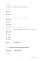

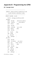
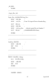
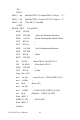
Table Of Contents
- Contents
- Chapter 1 Hardware Configuration
- Chapter 2 Connecting Peripherals
- 2.1 Introduction
- 2.2 1st (CN1) IDE Connectors
- 2.3 Floppy Drive Connector (CN3)
- 2.4 Parallel Port (CN4)
- 2.5 USB Ports (CN6,CN63,CN66,CN67)
- 2.6 VGA Connector CN7
- 2.7 DVI Connector VCN1 (optional)
- 2.8 Ethernet Connector (CN24)
- 2.9 Serial Ports (COM1: CN9/CN91; COM2: CN10 )
- 2.10 PS/2 Keyboard/Mouse Connector (CN11)
- 2.11 External Keyboard Connector (CN12)
- 2.12 CPU Fan Connector (CN68)
- 2.13 Front Panel Connectors (CN16, 17, 18, 19, 21&29)
- 2.14 ATX Feature Connector (CN20)
- 2.15 AC-97 Audio Interface (CN43)
- 2.16 Serial ATA Interface (SA0,SA1,SA2, and SA3)
- 2.17 Connecting to SNMP-1000 Remote Manager
- 2.18 Auxiliary 4-pin Power Connector (ATX1)
- 2.19 SCSI Daughterboard Extension Connector (CN30)
- 2.20 Case Open Connector (CN64)
- 2.21 Front Panel LAN Indicator Connector (CN65)
- 2.22 GPIO Pin Header (CN93)
- Chapter 3 Award BIOS Setup
- 3.1 Introduction
- 3.2 Entering Setup
- 3.3 Standard CMOS Setup
- 3.4 Advanced BIOS Features
- Figure 3.3: Advanced BIOS features screen
- 3.4.1 CPU Features
- 3.4.2 Hard Disk Boot Priority
- 3.4.3 Virus Warning
- 3.4.4 CPU L1 & L2 Cache
- 3.4.5 Hyper-Threading Technology
- 3.4.6 Quick Power On Self Test
- 3.4.7 First/Second/Third Boot Device
- 3.4.8 Boot Other Device
- 3.4.9 Swap Floppy Drive
- 3.4.10 Boot Up Floppy Seek
- 3.4.11 Boot Up NumLock Status
- 3.4.12 Gate A20 Option
- 3.4.13 Typematic Rate Setting
- 3.4.14 Typematic Rate (Chars/Sec)
- 3.4.15 Typematic Delay (msec)
- 3.4.16 Security Option
- 3.4.17 APIC Mode
- 3.4.18 MPS Version Control For OS
- 3.5 Advanced Chipset Features
- Figure 3.4: Advanced chipset features screen
- 3.5.1 DRAM Timing Selectable
- 3.5.2 CAS Latency Time
- 3.5.3 DRAM RAS# to CAS# Delay
- 3.5.4 DRAM RAS# Precharge
- 3.5.5 Precharge Delay (t RAS)
- 3.5.6 System Memory Frequency
- 3.5.7 System BIOS Cacheable
- 3.5.8 Video BIOS Cacheable
- 3.5.9 Memory Hole At 15M-16M
- 3.5.10 PCI-Express Root Port Func
- 3.5.11 On-Chip Video Memory Size
- 3.5.12 On-Chip Frame Buffer Size
- 3.5.13 FIXED Memory Size
- 3.5.14 DVMT Memory Size
- 3.5.15 Init Display First
- 3.6 Integrated Peripherals
- Figure 3.5: Integrated peripherals
- Figure 3.6: On-Chip IDE Device
- 3.6.1 IDE HDD Block Mode
- 3.6.2 IDE DMA Transfer Access
- 3.6.3 On-Chip IDE Device
- 3.6.4 SATA Mode
- 3.6.5 On-Chip Serial ATA
- 3.6.6 PATA IDE Mode
- 3.6.7 SATA Port
- Figure 3.7: Onboard Device
- 3.6.8 USB Controller
- 3.6.9 USB 2.0 Controller
- 3.6.10 USB Keyboard/Mouse Support
- 3.6.11 AC97 Audio
- 3.6.12 Onboard LAN1 Control
- 3.6.13 Onboard LAN2 Control
- 3.6.14 GPIO Function
- Figure 3.8: Super I/O Device
- 3.6.15 KBC Input Clock
- 3.6.16 Onboard FDC Controller
- 3.6.17 Onboard Serial Port 1
- 3.6.18 Onboard Serial Port 2
- 3.6.19 UART Mode Select
- 3.6.20 RxD, TxD Active
- 3.6.21 IR Transmission Delay
- 3.6.22 UR2 Duplex Mode
- 3.6.23 Use IR Pins
- 3.6.24 Onboard Parallel Port
- 3.6.25 Parallel Port Mode
- 3.6.26 EPP Mode Select
- 3.6.27 ECP Mode Use DMA
- 3.7 Power Management Setup
- Figure 3.9: Power management setup screen (1)
- 3.7.1 Power Supply Type
- 3.7.2 ACPI Function
- 3.7.3 Power Management
- 3.7.4 Video Off Method
- 3.7.5 Video Off In Suspend
- 3.7.6 Suspend Type
- 3.7.7 Modem Use IRQ
- 3.7.8 Suspend Mode
- 3.7.9 Soft-Off by PWR-BTTN
- 3.7.10 CPU THRM-Throttling
- 3.7.11 PowerOn by Modem
- 3.7.12 PowerOn by LAN
- 3.7.13 PowerOn by Alarm
- 3.7.14 Primary IDE 0 (1) and Secondary IDE 0 (1)
- 3.7.15 FDD, COM, LPT PORT
- 3.7.16 PCI PIRQ [A-D]#
- 3.7.17 PWRON After PWR-Fail
- 3.8 PnP/PCI Configurations
- 3.9 PC Health Status
- 3.10 Frequency / Voltage Control
- 3.11 Password Setting
- 3.12 Save & Exit Setup
- 3.13 Exit Without Saving
- Chapter 4 Chipset Software Install Utility
- Chapter 5 VGA Setup
- Chapter 6 LAN Configuration
- Chapter 7 USB 2.0 Configuration
- Chapter 8 Onboard Security Setup
- Appendix A Programming the watchdog
- Appendix B Programming the GPIO
- Appendix C Pin Assignments
- C.1 IDE Hard Drive Connector (CN1)
- C.2 Floppy Drive Connector (CN3)
- C.3 Parallel Port Connector (CN4)
- C.4 USB Connector (CN6, CN63, CN66, CN67)
- C.5 VGA Connector (CN7)
- C.6 VCN1 DVI connector
- C.7 COM1/COM2 RS-232 Serial Port (CN9/CN91/CN10)
- C.8 Keyboard and Mouse Connnector (CN11)
- C.9 External Keyboard Connector (CN68)
- C.10 CPU Fan Power Connector (CN14)
- C.11 Power LED (CN16)
- C.12 External Speaker Connector (CN17)
- C.13 Reset Connector (CN18)
- C.14 HDD LED Connector (CN19)
- C.15 ATX Feature Connector (CN20)
- C.16 ATX Soft Power Switch (CN21))
- C.17 H/W Monitor Alarm (CN22)
- C.18 AC-97 Audio Interface (CN43)
- C.19 SM Bus Connector (CN29)
- C.20 Case Open Connector (CN64)
- C.21 Front Panel LAN Indicator connector (CN65)
- C.22 GPIO Pin Header (SMD pitch=2.0mm) (CN93)
- C.23 System I/O Ports
- C.24 DMA Channel Assignments
- C.25 Interrupt Assignments
- C.26 1st MB Memory Map
- C.27 PCI Bus Map
PCA-6190 User’s Manual 86
;-----------------------------------------------------------
Dec dx ; Set second as counting unit
Mov al,0f5h
Out dx,al
Inc dx
In al,dx
And al,not 08h
Out dx,al
;-----------------------------------------------------------
Dec dx ; Set timeout interval as 10 seconds and start counting
Mov al,0f6h
Out dx,al
Inc dx
Mov al,10
Out dx,al
;-----------------------------------------------------------
Dec dx ; lock W83627HF
Mov al,0aah
Out dx,al
2. Enable watchdog timer and set 5 minutes as timeout interval
;-----------------------------------------------------------
Mov dx,2eh ; unlock W83627H
Mov al,87h
Out dx,al
Out dx,al
;-----------------------------------------------------------
Mov al,07h ; Select registers of watchdog timer
Out dx,al
Inc dx
Mov al,08h
Out dx,al