
User manual


51 Appendix C
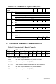
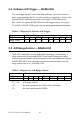
Table C-5 Register for MUX Scan Channel Control
CH3 ~ CH0 Stop scan channel number
CH0 the least significant bit (LSB) of the stop channel
CH3 the most significant bit (MSB)
CL3 ~ CL0 Start scan channel number
CL0 the least significant bit (LSB) of the start channel
CL3 the most significant bit (MSB)
The MUX scan register low nibble, CL3 to CL0, also acts as a pointer
when you program the A/D input range (see previous section). When you
set the MUX start channel to N, the range code written to the register
BASE+01H is for channel N.
Programming example for PCL-818HD
This BASIC code fragment sets the range for channel 5 to ±0.625 V:
200 OUT BASE+2, 5 'SET POINTER TO CH.5
210 OUT BASE+1, 3 'RANGE CODE=3 FOR ±0.625 V
Write MUX scan channel control
Bit # 7 6 5 4 3 2 1 0
BASE + 02H CH3 CH2 CH1 CH0 CL3 CL2 CL1 CL0
Note: The MUX start/stop channel changes each time
you change the input range. Do not forget to
reset the MUX start and stop channels to the cor-
rect values after you finish setting the range.