
Specifications


University of Hertfordshire
26
5.1.3 Operating Mode Setting
SW3 is set to select operating mode. When it is set to “A”, this card is compatible with the
easy-to-use PCL-748 IEEE-488 interface card except there is no real time clock. When SW3 is set
to “N”, this card becomes NI PC-II compatible.
For this project, SW3 is set to “A”.
5.1.4 DMA Level Setting
DMA (Direct Memory Access) is permitted by the PCL-848A/B GPIB Card. The DMA level is set
by JP1 and JP2. The JP1 is for DACK signal path while the JP2 is for DRQ. The settings of JP1 and
JP2 must be coincident. For example, if the JP1 is set to DACK 3, then JP2 must be set to DRQ 3.
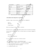
5.1.5 Interrupt Level (IRQ) Setting
The interrupt level 2 to level 7 is permitted in the PCL-848A/B card. The selection is made by
setting JP3.
Figure 5.2 IRQ setting (JP3)
Note Although the IRQ level can be set from IRQ 2 to IRQ 7 on the board, the firmware supports
IRQ 2, 3, 5, and 7 only. Initial setting is IRQ 7. (PCL-848C IEEE488 INTERFACE CARD C
LANGUAGE SUPPORT PACKAGE User's Manual, 2001)
The PCL-848A/B GPIB interface card is setup at the Initial setting: