User Manual PCM-4153 PC/104+ SBC w/AMD LX800, VGA, LCD, LAN, USB2.
Copyright The documentation and the software included with this product are copyrighted 2009 by Advantech Co., Ltd. All rights are reserved. Advantech Co., Ltd. reserves the right to make improvements in the products described in this manual at any time without notice. No part of this manual may be reproduced, copied, translated or transmitted in any form or by any means without the prior written permission of Advantech Co., Ltd. Information provided in this manual is intended to be accurate and reliable.
Declaration of Conformity FCC Class A Note: This equipment has been tested and found to comply with the limits for a Class A digital device, pursuant to part 15 of the FCC Rules. These limits are designed to provide reasonable protection against harmful interference when the equipment is operated in a commercial environment.
Technical Support and Assistance 1. 2. Visit the Advantech web site at www.advantech.com/support where you can find the latest information about the product. Contact your distributor, sales representative, or Advantech's customer service center for technical support if you need additional assistance.
Contents Chapter 1 General Information ............................1 1.1 1.2 1.3 Introduction ............................................................................................... 2 Features .................................................................................................... 2 Specifications ............................................................................................ 2 1.3.1 Standard PC/104 Biscuit SBC Functions...................................... 2 1.3.
3.10 3.11 3.12 3.5.8 Security Option ........................................................................... 16 Integrated Peripherals............................................................................. 17 3.6.1 IDE Master/Slave PIO/UDMA Mode, .......................................... 17 3.6.2 Integrated peripherals screen ..................................................... 17 3.6.3 Onboard LAN Control ................................................................. 17 3.6.
Chapter 6 Ethernet Interface ..............................39 6.1 6.2 6.3 Introduction ............................................................................................. 40 Installation of Ethernet driver .................................................................. 40 6.2.1 Installation for Windows XP ........................................................ 40 Further information..................................................................................
D.1 PCM-4153 User Manual GPIO Function: Its Call by Int15 Hook. ...................................................
Chapter 1 1 General Information This chapter gives background information on the PCM-4153.
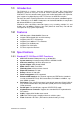
1.1 Introduction The PCM-4153 is a fanless, best-cost, performance PC/104+ SBC (Single Board Computer) geared to satisfy the needs for various industrial computing equipment. PCM-4153 is ideal for communication, gaming and medical applications that require flat panel support using digital displays with TTL interfaces and two Ethernet ports.
Chipset: AMD Geode LX800 Memory size: Optimized Shared Memory Architecture, support 64MB frame buffer using system memory Resolution: CRT resolution: up to 1600 x 1200 x 16 bpp at 100 Hz and up to 1024 x 768 x 32 bpp at 60 Hz for TFT LCD LCD interface: Supports up to 24-bit TFT LCD (TTL signal) Dual simultaneous display: CRT + LCD Chipset supports: 2 x 10/100Mbps - Intel 82551ER Interface: 2 x internal box header Standard IEEE 802.3u (100 BASE-T) protocol compatible 1.3.
1.4 Board Layout: Dimensions 0.00 90.17 Figure 1.1 Board layout: dimensions (component side) 95.89 87.63 87.63 62.91 23.63 14.49 8.26 8.26 90.17 102.87 2.02 0.00 12.70 4.45 97.69 0.00 Figure 1.
Chapter 2 2 Installation This chapter explains the setup procedures of the PCM-4153 hardware, including instructions on setting jumpers and connecting peripherals, switches and indicators. Be sure to read all safety precautions before you begin the installation procedure.
2.1 Jumpers The PCM-4153 has a number of jumpers that allow you to configure your system to suit your application. The table below lists the functions of the various jumpers. Table 2.
PCI VI/O POWER Setting Function (1-2) With +5V (2-3) With +3.3V (Default) Chapter 2 J5 Onboard connectors link the PCM-4153 to external devices such as hard disk drives, a keyboard, or floppy drives. The table below lists the function of each of the board’s connectors. Table 2.
2.3 Locating Connectors Figure 2.1 Connectors (component side) CN35 CN27 Figure 2.
You may configure your card to match the needs of your application by setting jumpers. A jumper is a metal bridge used to close an electric circuit. It consists of two metal pins and a small metal clip (often protected by a plastic cover) that slides over the pins to connect them. To “close” a jumper, you connect the pins with the clip. To “open” a jumper, you remove the clip. Sometimes a jumper will have three pins, labeled 1, 2 and 3. In this case you would connect either pins 1 and 2, or 2 and 3.
2.6 Flash The board provides onboard NAND Flash memory to replace CF socket. PCM-4153 support 1 GB flash, flash Endurance about 100K Program/Erase cycles and Data Retention for 10 Years . Flash controller with excellent performance and low cost, designed by this controller do not need to have additional mechanical parts, but have the properties of fully anti vibration and extremely low power consumption. On-board flash controller support IDE interface and support to PIO Mode 4. 2.
The board provides four serial ports: Four serial RS-232 ports in one Hirose 40 pin connector(CN30: COM1/2/3/4). It provides connections for serial devices or a communication network. You can find the pin assignments for the COM port connector in Appendix C. 2.11.1 Serial Port RS-422/485 (CN20) Table 2.3: Serial Port RS-422/485 (CN39) Setting Function 1-2 RS-232 (default) 3-4 RS-485 5-6 RS-422 2.
2.15 USB Connectors (CN15,CN17) The board provides up to four USB (Universal Serial Bus) ports using Plug and Play. The USB interfaces comply with High Speed USB specification Rev. 2.0 which supports 480Mbps transfer rate, and are fuse protected. The USB interface is accessed through two 5 x 2-pin flat-cable connectors. You will need an adapter cable if you use a standard USB connector. The adapter cable has a 5 x 2-pin connector on one end and a USB connector on the other.
Chapter 3 3 Award BIOS Setup
3.1 Introduction Award’s BIOS ROM has a built-in setup program that allows users to modify the basic system configuration. This type of information is stored in battery-backed memory (CMOS RAM) so that it retains the setup information when the power is turned off. 3.1.1 CMOS RAM Auto-backup and Restore The CMOS RAM is powered by an onboard button cell battery. When you finish BIOS setup, the data in CMOS RAM will be automatically backed up to Flash ROM.
Choose the “Standard CMOS Features” option from the “Initial Setup Screen” menu, and the screen below will be displayed. This menu allows users to configure system components such as date, time, hard disk drive, Video, Halt On, display, and memory. 3.4 Standard CMOS Setup Chapter 3 3.3 Standard CMOS Setup Award BIOS Setup 3.5 Advanced BIOS Features The “Advanced BIOS Features” screen appears when choosing the “Advanced BIOS Features” item from the “Initial Setup Screen” menu.
3.5.1 Virus Warning If enabled, a warning message and alarm beep activates if someone attempts to write here. The commands are “Enabled” or “Disabled.” 3.5.2 First/Second/Third/Other Boot Device The BIOS tries to load the OS with the devices in the sequence selected. Choices are: HDD, CDROM, LAN, Disabled. 3.5.3 Boot Up NumLock Status This feature selects the “power on” state for NumLock. The commands are “Enabled” or “Disabled.” 3.5.
3.6.1 IDE Master/Slave PIO/UDMA Mode, IDE Master/Slave PIO/UDMA Mode (Auto) has a master and a slave, making two IDE devices possible. Because each IDE device may have a different Mode timing (0, 1, 2, 3, 4), it is necessary for these to be independent. The default setting “Auto” will allow auto detection to ensure optimal performance. Award BIOS Setup 3.6.2 Integrated peripherals screen 3.6.3 Onboard LAN Control Options are Enable or Disable.
3.6.8 EPP Mode Select This field allows you to select EPP port type 1.7 or 1.9. 3.6.9 ECP Mode Use DMA This selection is available only if you select “ECP” or “ECP + EPP” in the Parallel Port Mode field. In ECP Mode Use DMA, you can select DMA channel 1, DMA channel 3, or Disable. Leave this field on the default setting. 3.7 Power Management Setup The power management setup controls the CPU card’s “green” features to save power. The following screen shows the manufacturer’s defaults: Figure 3.
When system is in suspend, video will turn off. 3.7.4 Modem Use IRQ This determines the IRQ in which the MODEM can use.The choices: 3, 4, 5, 7, 9, 10, 11, NA. Chapter 3 3.7.3 Video Off In Suspend 3.7.5 HDD Power Down 3.7.6 PowerOn By Modem When Enabled, an input signal on the serial Ring Indicator (RI) line (in other words, an incoming call on the modem) awakens the system from a soft off state. The choices: Enabled, Disabled. 3.7.
3.8 PnP/PCI Configurations 3.8.1 PnP OS Installed Select Yes if you are using a plug and play capable operating system. Select No if you need the BIOS to configure non-boot device Figure 3.4: PnP/PCI configurations screen 3.8.2 Reset Configuration Data Default is Disable. Select Enable to reset Extended System Configuration Data (ESCD) if you have installed a new add-on and system configuration has caused such a conflict that OS cannot boot. 3.8.
This is to check the PC health, ex: currenten CPU temperature. 3.9.1 PC Health Status Screen Award BIOS Setup 3.10 Password Setting To change the password: 1. Choose the “Set Password” option from the “Initial Setup Screen” menu and press . The screen will display the following message Please Enter Your Password Press . 2. Chapter 3 3.
3.11 Save & Exit Setup If you select this and press , the values entered in the setup utilities will be recorded in the CMOS memory of the chipset. The microprocessor will check this every time you turn your system on and compare this to what it finds as it checks the system. This record is required for the system to operate. 3.12 Exit Without Saving Selecting this option and pressing lets you exit the setup program without recording any new values or changing old ones.
Chapter 4 4 PCI SVGA/LCD Setup This chapter details the software configuration information. It shows you how to configure the card to match your application requirements. The AWARD System BIOS is covered in Chapter 4.
4.1 Introduction The board has an onboard AMD Geode LX800 chipset for its PCI/SVGA controller. It supports TFT LCD displays and conventional analog CRT monitors with 64MB frame buffer shared with system memory. The VGA controller can drive CRT displays with resolutions up to 1600 x 1200 x 16 bpp at 100 Hz and up to 1024 x 768 x 32 bpp at 60 Hz for TFT LCD. 4.1.1 Display Type The board can be set in one of three configurations: on a CRT, on a flat panel display, or on dual simultaneous display.
11 R2 12 GND D20 13 R3 30 D21 14 R4 31 D22 15 R5 32 D23 16 GND 17 GND 18 GND 19 G0 19 D10 20 G1 20 D11 21 G2 21 D12 22 GND 23 G3 22 D13 24 G4 23 D14 25 G5 24 D15 26 GND 33 GND 27 GND 28 GND 33 GND 29 B0 11 D2 30 B1 12 D3 31 B2 13 D4 32 GND 34 GND 33 B3 14 D5 34 B4 15 D6 35 B5 16 D7 36 GND 34 GND 37 ENAB 37 DE 38 NC 39 VCC 5 +3.3 V 40 VCC 6 +3.
4.3.1 Installation Chipset AES Driver 1. Open device manager, right click on entertainment then, click on properties 2. Go to driver page and click on update driver. 3. Click on install from specific folder and click on next.
5. Click on next. 6. Click on finish. PCI SVGA/LCD Setup Click on browse and select target folder, then, click OK. Chapter 4 4.
4.3.2 Installation of VGA Driver 1. Right click on video, and click “ Properties”. 2. Go to driver page and click on update driver.
4. Click on browse and select target folder, then click OK. 5. Click on next, then click on finish. 29 PCI SVGA/LCD Setup Click on install from specific folder and click on next. Chapter 4 3.
6. Then click on continue anyway. 7. Click on finish.
The system may detect PCI bridge automatically. If the question mark is shown on device manager, please install the driver as below: 1. Click “Add Hardware Wizard” and add new hardware wizard Chapter 4 4.3.
2. Search the right directory of PCI bridge for IT8888G driver. 3. Installation finished. 4.4 Further Information For further information about the AGP/VGA installation of your PCM-4153, including driver updates, troubleshooting guides and FAQ lists, visit the following web resources: Intel website: www.intel.com Advantech websites: www.advantech.com www.advantech.com.
Chapter 5 5 Audio Setup The board is equipped with an audio interface that records and plays back CD-quality audio. This chapter provides instructions for installing the software drivers included on the audio driver diskettes.
5.1 Introduction The onboard audio interface provides high-quality stereo sound by using the AMD LX800 audio controller. The audio interface can record, compress, and play back voice, sound, and music with built-in mixer control. 5.2 Driver Installation 5.2.1 Before You Begin Please read the instructions in this chapter carefully before you attempt installation. The audio drivers for the board are located on the audio driver CD.
Open device manager, right click on audio and click on “properties”. 2. Go to driver page and click on update driver. 3. Click on install from specific folder and click on next. 35 Audio Setup 1. Chapter 5 5.2.
4. Click on browse and select target folder, then click OK. 5. Click on next.
7. Click on finish. Audio Setup Click on continue anyway. Chapter 5 6.
PCM-4153 User Manual 38
Chapter 6 6 Ethernet Interface This chapter provides information on Ethernet configuration.
6.1 Introduction The board is equipped with a high performance 32-bit Ethernet chipset which is fully compliant with IEEE 802.3 100 Mbps CSMA/CD standards. It is supported by major network operating systems. With 100Base-T compatible. The network boot feature can be utilized by incorporating the boot ROM image files for the appropriate network operating system. The boot ROM BIOS files are combined with system BIOS, which can be enabled/disabled in the BIOS setup. 6.
4. Choose Hardware Device “Ethernet Controller” Ethernet Interface Click “Add new hardware wizard” and prepare to install network function Chapter 6 3.
5. 6. 7. Insert the CD into D: drive a. Fill in the Find the LAN chipset folder at the directory of PCM-4153 win2000 folder from CD ROM drive b. Click “OK”. 8.
Click “Next” Chapter 6 9. Ethernet Interface 10. 11. Make sure the configurations of relative items are set correctly 12.
6.3 Further information Intel website: www.intel.com Advantech websites: www.advantech.com www.advantech.com.
Appendix A A Pin Assignments This appendix contains information of a detailed or specialized nature.
A.1 Jumper and Connector Tables Table A.1: J2, DOTREF Select Part Number 1653002101 Footprint JH2X1V-2M Description PIN HEADER 2*1P 180D (M) 2.0 mm DIP SQUARE W/O Pb Setting Function (1 - 2) External NL Internal Table A.2: J3, Clear CMOS Part Number 1653003101 Footprint JH3X1V-2M Description PIN HEADER 3*1P 180D (M)SQUARE 2.0 mm Setting Function (1 - 2) BAT (default) (2 - 3) Clear-CMOS Table A.
Part Number 1653003101 Footprint JH3X1V-2M Description PIN HEADER 3*1P 180D(M) 2.0 mm DIP SQUARE W/O Pb Setting Function (1-2) Slave (default) (2-3) Master Table A.5: J5, PCI VI/O POWER Part Number 1653003101 Footprint JH3X1V-2M Description PIN HEADER 3*1P 180D (M)SQUARE 2.0mm Setting Function (1 - 2) With +5 V (2 - 3) With +3.3 V Table A.6: CN38, Power Input 8 1 Part Number 1655204030 Footprint PWR-B4PV Description PIN HEADER DIP 8*1P 180D(M) 2.
Table A.7: CN4, TFT LCD I/F Part Number 1653920200 Footprint SPH20X2 Description *CONN. DF13-40DP-1.25 V Pin Pin Name Signal Type Signal Level 1 +5 V PWR +5 V 2 +5 V PWR +5 V 3 GND GND - 4 GND GND - 5 +3.3V PWR +3.3 V 6 +3.3V PWR +3.3 V 7 TV-CLK CLK48M +3.3 V 8 GND GND - 9 D0 I/O +5 V 10 D1 I/O +5 V 11 D2 I/O +5 V 12 D3 I/O +5 V 13 D4 I/O +5 V 14 D5 I/O +5 V 15 D6 I/O +5 V 16 D7 I/O +5 V 17 D8 I/O +3.
HS OUT +3.3 V 39 RST OUT +3.3 V 40 FP OUT +3.3 V Table A.8: CN5, Inverter Power 5 4 3 2 1 Part Number 1655305020 Footprint WHL5V-2M Description WAFER BOX 2.0 mm 5P 180D MALE W/LOCK Pin Pin Name Signal Type Signal Level 1 +12 V PWR +12 V 2 GND GND - 3 ENABKL OUT +3.3 V 4 VBR OD +3.3 V 5 +5 V PWR +5 V Table A.9: CN6, SMBus 2 1 Part Number 1653002101 Footprint JH2X1V-2M Description PIN HEADER 2*1P 180D (M)SQUARE 2.
Table A.11: CN33-Battery Connector Pin Function 1 VBAT power 2 GND Table A.12: CN36, GPIO1 5 4 3 2 1 Part Number 1653005261 Footprint JH5X2S-2M Description PIN HEADER SMD 5*1P 180D(M) 2.54mm Pin Pin Name Signal Type Signal Level 1 +5V PWR +5 V 2 GPIO0 I/O +5 V 3 GPIO1 I/O +5 V 4 GPIO2 I/O +5 V 5 GPIO3 I/O +5 V Table A.13: CN37, GPIO2 5 4 3 2 1 Part Number 1653005261 Footprint JH5X2S-2M Description PIN HEADER SMD 5*1P 180D(M) 2.
GND GND - 3 D7 I/O +5V 4 D8 I/O +3.
Table A.15: CN27, CRT 1654515304 Footprint DBVGA-VF5M 12 1 Part Number Description CONN. 12P 90D(F) SMD 1.25 mm Pin Pin Name Signal Type Signal Level 1 GND GND - 2 R OUT Analog 3 G OUT Analog 4 B OUT Analog 5 GND GND - 6 +5V PWR - 7 DDAT OD I/O +2.5 V 8 DCLK OD I/O +2.5 V 9 GND GND - 10 HSYNC OUT +2.5 V 11 VSYNC OUT +2.5 V 12 GND - - Table A.
10 5 9 8 4 3 7 2 6 1 Part Number 1653005260 Footprint JH5X2S-2M Description PIN HEADER 5*2P 180D(M) 2.0 mm SMD IDIOT-PROOF Pin Pin Name Signal Type Signal Level 1 +5V PWR +5V 2 +5V PWR +5V 3 P2- I/O USB 4 P3- I/O USB 5 P2+ I/O USB 6 P3+ I/O USB 7 GND GND - 8 GND GND - 9 GND GND - 10 NC - - Table A.18: CN30, COM1/2/3/4 39 37 3 1 40 38 4 2 Part Number 1653000221 Footprint BH20X2SV-2.
18 RI#2 In +5 V 19 GND GND - 20 GND GND - 21 DCD#3 In +5 V 22 DSR#3 In +5 V 23 RXD3 In +5 V 24 RTS#3 I/O +5 V 25 TXD3 Out +5 V 26 CTS#3 In +5 V 27 DTR#3 I/O +5 V 28 RI#3 In +5 V 29 GND GND - 30 GND GND - 31 DCD#4 In +5 V 32 DSR#4 In +5 V 33 RXD4 In +5 V 34 RTS#4 I/O +5 V 35 TXD4 Out +5 V 36 CTS#4 In +5 V 37 DTR#4 I/O +5 V 38 RI#4 In +5 V 39 GND GND - 40 GND - - 26 24 25 23 Table A.
PD6 I/O +5 V 16 GND GND - 17 PD7 I/O +5 V 18 GND GND - 19 ACK# In +5 V 20 GND GND - 21 BUSY In +5 V 22 GND GND - 23 PE In +5 V 24 GND GND - 25 SLCT In +5 V 26 NC - - Table A.20: CN20, RS422/485 4 3 2 1 Part Number 1653004101 Footprint JH4X1V-2M Description PIN HEADER 4*1P 180D(M) SQUARE 2.0 mm Pin Pin Name Signal Type Signal Level 1 422-RXD- In +5 V 2 422-RXD+ In +5 V 3 485-422-TXD+ Out +5 V 4 485-422-TXD- Out +5 V Table A.
Table A.22: CN34, AUDIO-IN 5 4 3 2 1 Part Number 1655303020 Footprint WHL3V-2M Description WAFER BOX 2.0 mm 3P 180D w/LOCK Pin Pin Name Signal Type Signal Level 1 LIN-IN-R IN Analog 2 GND GND - 3 LIN-IN-L IN Analog 4 GND GND - 5 MIC-IN IN Analog Table A.23: CN23, ISA -5V & -12V Input 3 2 1 Part Number 1653003101 Footprint JH3X1V-2M Description PIN HEADER 3*1P 180D (M)SQUARE 2.
2 4 1 6 8 10 3 5 7 9 Part Number 1653205260 Footprint BH5X2SV Description BOX HEADER SMD 5*2 180D (M) 2.0 mm Pin Pin Name Signal Type Signal Level 1 +3.3 V PWR +3.3 V 2 LAN2-ACTLED IN Analog 3 LAN2-RX+ IN Analog 4 LAN2-RX- IN Analog 5 LAN2-LILED IN Analog 6 LAN2-LCT I/O Analog 7 N/A - - 8 LAN2-LCT I/O Analog 9 LAN2-TX+ OUT Analog 10 LAN2-TX- OUT Analog Table A.
PCM-4153 User Manual 58
Appendix B B System Assignments This appendix contains information of a detailed nature.
B.1 System I/O Ports Table B.1: System I/O Ports Addr.
Table B.2: 1st MB Memory Map Addr. range (Hex) Device F0000h - FFFFFh System ROM *CC000h - EFFFFh Unused (reserved for Ethernet ROM) C0000h - CBFFFh Expansion ROM (for VGA BIOS) B8000h - BFFFFh CGA/EGA/VGA text B0000h - B7FFFh Unused A0000h - AFFFFh EGA/VGA graphics 00000h - 9FFFFh Base memory * If Ethernet boot ROM is disabled (Ethernet ROM occupies about 16 KB) * E0000 - EFFFF is reserved for BIOS POST B.3 DMA Channel Assignments Table B.
B.4 Interrupt Assignments Table B.
Appendix C C Mechanical Drawings
C.1 Mechanical Drawings 0.00 90.17 Figure C.1 PCM-4153 Mech drawing (comp side) 95.89 87.63 87.63 62.91 8.26 8.26 102.87 90.17 0.00 12.70 97.69 0.00 Figure C.
Appendix D Prog.
D.1 GPIO Function: Its Call by Int15 Hook.
D.2 Watchdog Timer: ;The SCH3114 Runtime base I/O address is 800h ;Setting WatchDog time value location at offset 66h ;If set value "0", it is mean disable WatchDog function. Superio_GPIO_Port = 800h mov dx,Superio_GPIO_Port + 66h mov al,00h out dx,al .model small .486p .stack 256 .data SCH3114_IO EQU 800h .code org 100h .
;66H ;WDT timer time-out value ;bit[7:0]=0~255 ;==================================================== mov dx,SCH3114_IO + 66h mov al,01h out dx,al ;==================================================== ;bit[0] status bit R/W ;WD timeout occurred =1 ;WD timer counting = 0 ;==================================================== mov dx,SCH3114_IO + 68h mov al,01h out dx,al .
Appendix D Prog.
www.advantech.com Please verify specifications before quoting. This guide is intended for reference purposes only. All product specifications are subject to change without notice. No part of this publication may be reproduced in any form or by any means, electronic, photocopying, recording or otherwise, without prior written permission of the publisher. All brand and product names are trademarks or registered trademarks of their respective companies. © Advantech Co., Ltd.