User Manual PCM-9588 Intel® Celeron® M EBX SBC with DVI/ TTL/ VGA/ LVDS/ LAN/ 6 COM/ 2 SATA / 6 USB2.
Copyright This document is copyrighted, ©2009. All rights are reserved. The original manufacturer reserves the right to make improvements to the products described in this manual at any time without notice. No part of this manual may be reproduced, copied, translated or transmitted in any form or by any means without the prior written permission of the original manufacturer. Information provided in this manual is intended to be accurate and reliable.
Product Warranty (2 years) Warranty Period ADVANTECH aims to meet the customer's expectations for post-sales service and support; therefore, in addition to offering 2 years global warranty for ADVANTECH's standard products, a global extended warranty service is also provided for customers upon request. ADVANTECH customers are entitled to a complete and prompt repair service beyond the standard 2 years of warranty.
Phoenix Operation User Notes Issue date: OCT 2008 Terms & Conditions TERMS (Lifetime Factors) Advantech’s Phoenix Operation is a screening service to test a system’s ability to operate under a wide range of temperatures. Naming rules for Advantech’s Phoenix Operation: 1. Z (Advantech Phoenix Gold): A product bearing this indicator (Z) has already passed Advantech’s -20 ~ 80°C high/low temperature and burn-in test, based on Advantech’s internal screening process. 2.
Declaration of Conformity FCC Class A This device complies with the requirements in part 15 of the FCC rules: Operation is subject to the following two conditions: 1.This device may not cause harmful interference, and 2. This device must accept any interference received, including interference that may cause undesired operation This equipment has been tested and found to comply with the limits for a Class A digital device, pursuant to Part 15 of the FCC Rules.
Packing List Before installation, please ensure the following items have been shipped: 1 PCM-9588 SBC 1 Startup manual 1 Utility CD 1 mini jumper pack 9689000002 Ordering information Model Number Description PCM-9588T-M0A1E PCM-9588F-S0A1E Intel C-M 600M w/TTL/CRT/6 COM/Audio/2SATA/16 GPIO Intel C-M 1.
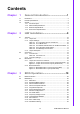
Contents Chapter Chapter 1 General Introduction ...........................1 1.1 1.2 1.3 Introduction ............................................................................................... 2 Product Specifications............................................................................... 2 Chipset ...................................................................................................... 2 1.3.1 Functional Spec. ...................................................................
Chapter 4 S/W Introduction & Installation........ 37 4.1 4.2 4.3 S/W Introduction ..................................................................................... 38 Driver Installation .................................................................................... 38 4.2.1 Windows XP Professional........................................................... 38 4.2.2 Other OS..................................................................................... 38 SUSI Application Library ........
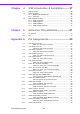
A.19 A.20 A.21 A.22 A.23 A.24 A.25 A.26 A.27 A.28 A.29 A.30 A.31 A.32 Table A.18:CN24: SIR Connector............................................... 66 CN25: PS2 Keyboard/Mouse connector ................................................. 67 Table A.19:CN25: PS2 Keyboard/Mouse connector................... 67 CN26: CF TYPEII connector ................................................................... 67 Table A.20:CN26: CF TYPEII connector .................................... 67 CN27: -V5 and -V12 connector .
E.2 E.3 E.4 PCM-9588 User Manual Table E.1: System I/O Ports ...................................................... 96 1st MB Memory Map............................................................................... 97 Table E.2: Table C.2: 1st MB memory map............................... 97 DMA Channel Assignments .................................................................... 97 Table E.3: DMA channel assignments....................................... 97 Interrupt assignments ......................
Chapter 1 1 General Introduction This chapter gives background information on PCM-9588.
1.1 Introduction Fanless design, Intel® Celeron® M Processor on board type EBX form factor standard, supports PC/104-Plus One SODIMM up to 2GB DDR2 400 MHz (910GMLE) Display Combination: CRT+ LVDS / DVI+ LVDS/ DVI+ CRT/ CRT+ TTL/ DVI+TTL 10/100 Mbps Ethernet support UL60601 Design, GIGA LAN optional Supports Wake-on-LAN, Wake-on-Modem Supports LCD backlight turn-off function Supports ATX/ AT power modes AC97 Audio on board 6 COM (Supports Auto flow control), 2 SATA, 6 USB 2.
VGA Analog CRT DAC interface support Supports max DAC frequency up to 400 MHz 24-bit RAMDAC support DDC2B compliant Digital/Analog Converter for CRT: QXGA (2048x1536) DVI able to drive a DFP display at a pixel rate of up to 165MHz supporting UXGA (1600x1200) resolution displays.
1.3.1.3 Chipset (ICH6M) I/O: LPT 1 RS-232 4 RS-232/422/485 2 (Default RS-422/485, RS-232 by optional request) K/B 1 Mouse 1 USB 6 x USB2.0 Audio AC97, Line-in, Line-out, Mic-in, speaker out (R/L) GPIO 16-bit general purpose input/output IRDA 115 kbps (optional by request) shared from COM2 South Bridge Controller Hub Intel ICH6M PCI Compliant Supports 33MHz PCI 2.
Fan Programmable automatic fan monitor based on temperature. System FAN Power Connector x 1 It should be added near by the CPU socket Connector type: 2.0mm Wafer box 3x1 Default is +12V Fan Pin1: GND Pin2: +12V Pin3: Fan speed signal input Temperature monitors system/CPU temperature and voltage status Voltage 2.5V,Vcore, 12V, 5V, 3.3V, Chapter 1 SMSC3106 Super I/O Chipset SMSC3106 General Introduction Fan speed monitor N/A Temperature Yes 1.3.2 Mechanical Specifications 1.3.2.
1.3.3.2 Power supply Current PCM-9588 AT Power Consumption Test Condition: OS - WindowsXP SP2 Add-in Card - None CF Card - Transcent 1G MiniPCI Card - None HDD - 160GB SATA *1 BIOS - 9588x049 KeyBoard/Mouse - USB or PS/2 Interface Display - CRT CPU type Status DOS Idle Intel Cele- S3 ron M Win Idle 600MHz Win HCT11.2 CPU type Status DOS Idle Intel Cele- S3 ron M 1 Win Idle GHz Win HCT11.2 +V3.3 +V5SB +V5 +V12 +V3.3 +V5SB +V5 DDRII 512MB/533MHz +V12 +V3.
Chapter 1 1.3.3.3 RTC Battery Typical Voltage: 3.0V Normal discharge capacity: 196mAh 1.3.4 Environment Specifications 1.3.4.1 Operating temperature 0 ~ 60° C (32 ~ 140° F) General Introduction 1.3.4.2 Operating Humidity 0% ~ 90% Relative Humidity, non-condensing 1.3.4.3 Storage temperature Standard products (0 ~ 60° C) Storage temperature: -20 ~ 70° C 1.3.4.
PCM-9588 User Manual 8
Chapter 2 2 H/W Installation This chapter explains the setup procedures of the PCM-9588 hardware, including instructions on setting jumpers and connecting peripherals, switches, indicators and mechanical drawings.
2.1 Jumpers 2.1.1 Jumper list JP1 JP4 JP6 JP8 JP9 VIO Select for PCI and ISA Slot CMOS Clear RS422/RS485 Select for COM5 and COM6 LCD Panel Power Select Backlight Control Select 2.1.2 Jumper Settings: Table 2.1: JP1: VIO Select for PCI and ISA slot Part Number 1653003100 Footprint PH_3x1V_2.54mm Description PIN HEADER 3*1P 180D(M) 2.54mm DIP WO/Pb Setting Function (1-2) +V5 (2-3) +V3.3 Table 2.
Part Number 1653003101 Footprint JH3X1V-2M Description PIN HEADER 3*1P 180D(M) 2.0mm DIP SQUARE W/O Pb Setting Function (1-2) +V5 (2-3) +V3.3 Part Number 1653003101 Footprint JH3X1V-2M Description PIN HEADER 3*1P 180D(M) 2.0mm DIP SQUARE W/O Pb Setting Function (1-2) PWM Control (2-3) Voltage Control 2.1.3 Jumper description Cards can be configured by setting jumpers. A jumper is a metal bridge used to close an electric circuit.
2.2 Connectors 2.2.1 Connector list Table 2.
2.2.2.4 Inverter connector (CN6) PCM-9588 can provide +5V and +12V and signal to LCD inverter board via CN6. 2.2.2.5 VGA connector (CN8) The DB15-pin female connector is provided for video monitors. 2.2.2.6 LVDS connector (CN9) Low-voltage differential signaling, or LVDS, is an electrical signaling system that can run at very high speeds over inexpensive twisted-pair copper cables.
2.2.2.11 IDE Connector (CN16) The board provides 1 IDE channel, and is designed for one Enhanced Integrated Device Electronics hard disk drive or CDROM to the board's internal controller and one CF card. The IDE controller uses a PCI interface. This advanced IDE controller supports faster data transfer, PIO mode 4, Multi-word DMA mode 2 and an Ultra ATA-133 interface. How to connect the hard drive to CN16 1. Connect one end of the cable to CN16.
2.2.2.21 DDR2 SODIMM Socket (CN29) A SO-DIMM, or small outline dual in-line memory module, is a type of computer memory built using integrated circuits.PCM-9588 has 1 x 200 pin SO-DIMM and can support memory size up to 2GB. 2.2.2.23 SATA Connector (CN31 and CN32) PCM-9588 supports Serial ATA via CN31 and CN32. Data transfer rates up to 150 MB/s, enabling very fast data and file transfer, and independent DMA operation on two ports.
2.3 Mechanical 2.3.1 Jumper and Connector Locations Figure 2.1 Jumper and Connector Layout (Component Side) Figure 2.
193.04 [7.600] 198.12 [7.800] 144.78 [5.700] 78.74 [3.100] 71.12 [2.800] 36.20 [1.425] 0.00 [0.000] Chapter 2 2.3.2 Board Dimensions 140.97 [5.550] 138.44 [5.450] 135.89 [5.350] 41.98 [1.653] 7.63 [0.300] 0.98 [0.038] 0.00 [0.000] 5.08 [0.200] 193.04 [7.600] 147.32 [5.800] 152.40 [6.000] 62.23 [2.450] 67.31 [2.650] 68.58 [2.700] 55.80 [2.197] 14.80 [0.583] 5.08 [0.200] 0.00 [0.000] 2.55 [0.100] 0.00 [0.000] 2.53 [0.100] 0.00 [0.000] 52.29 [2.059] 144.78 [5.700] 162.76 [6.408] 193.04 [7.
PCM-9588 User Manual 18
Chapter 3 BIOS Operation 3
3.1 BIOS Introduction Advantech provides the full-featured AwardBIOS 6.0 which delivers superior performance, compatibility and functionality that manufactures of Industrial PC and Embedded boards demand; it's many options and extensions let you customize your products to a wide range of applications and target markets. The modular, adaptable AwardBIOS 6.
Press to enter AwardBIOS CMOS Setup Utility, the Main Menu will appear on the screen. Use arrow keys to select among the items and press to accept or enter the sub-menu. Chapter 3 3.2.1 Main Menu BIOS Operation Standard CMOS Features This setup page includes all the items in standard compatible BIOS. Advanced BIOS Features This setup page includes all the items of Award BIOS enhanced features.
3.2.2 Standard CMOS Features Date The date format is , , , . Weekday From Sun to Sat, determined and display by BIOS only Month From Jan to Dec. Day From 1 to 31 Year From 1999 through 2098 Time The times format in , base on the 24-hour time. IDE Channel 0 Master/Slave IDE HDD Auto-Detection Press "Enter" for automatic device detection. IDE Channel 1 Master/Slave IDE HDD Auto-Detection Press "Enter" for automatic device detection.
Extended Memory The POST of the BIOS will determine the amount of extended memory (above 1MB in CPU's memory address map) installed in the system. Total Memory This item displays the total system memory size. 3.2.3 Advanced BIOS Features Chapter 3 BIOS Operation CPU Feature This item allows user to adjust CPU features, CPU ratio, VID and Thermal and special feature like XD flag.
First / Second / Third / Other Boot Drive Floppy Assign this boot device priority to Floppy. LS120 Assign this boot device priority to LS120. Hard Disk Assign this boot device priority to Hard Disk. CDROM Assign this boot device priority to CDROM. ZIP Assign this boot device priority to ZIP. USB-FDD Assign this boot device priority to USB-FDD. USB-ZIP Assign this boot device priority to USB-ZIP. USB-CDROM Assign this boot device priority to USB-CDROM.
Chapter 3 3.2.4 Advanced Chipset Features BIOS Operation Note! This "Advanced Chipset Features" option controls the configuration of the board's chipset; items on this page depend on the chipset installed. It is strongly recommended only technical users make changes to the default settings.
This item allows the video BIOS to be cached to allow faster execution and better performance. Memory Hole At 15M-16M [Disabled] This item reserves 15MB-16MB memory address space to ISA expansion cards that specifically require the setting. Memory from 15MB-16MB will be unavailable to the system because of the expansion cards can only access memory at this area. PEG/Onboard VGA Control [Auto] This item allows the user to select whether onboard graphics processor or the PCI Express card.
This "Integrated Peripherals" option controls the configuration of the board's chipset, includes IDE, ATA, SATA, USB, AC97, MC97 and Super IO and Sensor devices; this page may vary according to the chipset installed.
Onboard Serial port 1 [3F8] This item allows user to adjust serial port 1 address. Serial port 1 Use IRQ [IRQ3] This item allows user to adjust serial port 1 IRQ. Onboard Serial port 2 [3E8] This item allows user to adjust serial port 2 address. Serial port 2 Use IRQ [IRQ4] This item allows user to adjust serial port 2 IRQ. Serial port 3 [2F8] This item allows user to adjust serial port 3 address. Serial 3 IRQ [IRQ5] This item allows user to adjust serial port 3 IRQ.
Parallel Port Mode [Standard] This item allows user to adjust parallel port mode. ECP Mode Use DMA [3] This item allows user to adjust ECP DMA resource. Chapter 3 3.2.6 Power Management Setup BIOS Operation Note! This "Power management Setup" option may be used to configure the system to most effectively energy conservation, while still operating in a manner consistent with intended computer use style.
User Define Allows user to set each mode individually. Suspend Mode= Disabled or 1 min ~1 hr. HDD Power Down [Disabled] This item allows user to determine the time of system inactivity, the hard disk drive will be powered down. Mode= Disabled or 1 min ~ 15 min Video Off Method [DPMS] This item allows user to determine the manner is which the monitor is blanked. V/H SYNC+Blank This option will cause system to turn off vertical and horizontal synchronization ports and write blanks to the video buffer.
Chapter 3 3.2.7 PnP/PCI Configurations BIOS Operation Note! This "PnP/PCI Configurations" option sets up the IRQ and DMA (both PnP and PCI bus assignments). Init Display First [PCI Slot] This item is setting for start up Video output from PCI or Onboard device. Reset Configuration Data [Disabled] This item allow user to clear any PnP configuration data stored in the BIOS.
3.2.8 PC Health Status Note! This "PC Health Status" page reports the thermal, fan and voltage status of the board. This page may vary according to the chipset installed. Shutdown Temperature [Disabled] This item enables users to set the limitation of CPU temperature, the range is from 85° C and 100° C. Current System/CPU Temp [Show Only] This item displays current system and CPU temperature. 2.5 V / 3.3 V / 5 V / 12 V [Show Only] This item displays current CPU and system Voltage.
Chapter 3 3.2.9 Frequency/voltage Control BIOS Operation Note! This "Frequency/Voltage Control" option controls the CPU Host and PCI frequency, this page depends on the CPU and chipset installed; some items will show up only when you install a processor which supports those functions. Spread Spectrum [Disabled] This item enables users to set the spread spectrum modulation, if desired. 3.2.
Note! Load Optimized Defaults loads the default system values directly from ROM. If the stored record created by the Setup program should ever become corrupted (and therefore unusable), these defaults will load automatically when you turn PCM-9588 system on. 3.2.11 Set Password Note! To enable this feature, you must first go to the Advanced BIOS Features menu, choose the Security Option, and select either Setup or System, depending on which aspect you want password protected.
3.2.12 Save & Exit Setup Note! Typing "Y" will quit the BIOS Setup Utility and save user setup value to CMOS. Typing "N" will return to BIOS Setup Utility. 35 PCM-9588 User Manual BIOS Operation To Disable Password 1. Choose the Set Password option from the CMOS Setup Utility main menu and press . 2. When you see “Enter Password”, enter the existing password and press . 3. You will see “Confirm Password”. Type it again, and press . 4.
3.2.13 Quit Without Saving Note! Typing "Y" will quit the BIOS Setup Utility without saving to CMOS. Typing "N" will return to BIOS Setup Utility.
Chapter 4 4 S/W Introduction & Installation Sections include: S/W Introduction Driver Installation SUSI Application Library
4.1 S/W Introduction The mission of Advantech Embedded Software Services is to "Enhance quality of life with Advantech platforms and Microsoft Windows® embedded technology." We enable Windows® Embedded software products on Advantech platforms to more effectively support the embedded computing community. Customers are freed from the hassle of dealing with multiple vendors (hardware suppliers, system integrators, embedded OS distributors) for projects.
4.3.1 SUSI Introduction To make hardware easier and convenient for programmers to access, Advantech has released a suite of API (Application Programming Interface) in the form of a program library. The program library is called Secured and Unified Smart Interface or SUSI for short. Application programmers can invoke the functions exported by SUSI instead of calling the drivers directly. The benefit of using SUSI is portability. The same set of API is defined for different Advantech hardware platforms.
4.3.2.4 The VGA Control API There are two kinds of VGA control APIs, backlight on/off control and brightness control. Backlight on/off control allows a developer to turn on or off the backlight, and to control brightness smoothly. 4.3.2.5 The Watchdog API A watchdog timer (abbreviated as WDT) is a hardware device which triggers an action, e.g. rebooting the system, if the system does not reset the timer within a specific period of time.
Manual Installation: You can add the SUSI Library into the image by editing any bib file. First open project.bib in the platform builder. Add this line to the MODULES section of project.bib Susi.dll $(_FLATRELEASEDIR)\Susi.dllNK SH If you want to run the window-based demo, add following line: SusiTest.exe $(_FLATRELEASEDIR)\SusiTest.exe If you want to run the console-based demo, add following lines: Watchdog.exe $(_FLATRELEASEDIR)\Watchdog.exe NK S GPIO.exe$(_FLATRELEASEDIR)\GPIO.exeNK S SMBUS.
4.3.4 SUSI Sample Programs 4.3.4.1 Sample Programs The sample programs demonstrate how to incorporate SUSI into your program. There are sample programs for two categories of operating system, i.e. Windows XP and Windows CE. The sample programs run in graphics mode in Windows XP and Windows CE. The sample programs are described in the subsections below. 4.3.4.2 Windows Graphics Mode There are sample programs of Windows in graphics mode for two categories of operating system, i.e. Windows CE and Windows XP.
Chapter 4 4.3.4.4 GPIO Test Read Single Input Pin – Click the radio button- Single-Pin. – Key in the pin number to read the value of the input pin. The Pin number starts from '0'. – Click the READ GPIO DATA button and the status of the GPIO pin will be displayed in (R/W) Result field. Test Read Multiple Input Pin – Click the radio button- Multiple-Pins. – Key in the pin number from ‘0x01’ to ‘0x0F’ to read the value of the input pin. The pin numbers are ordered bitwise, i.e.
Test Write Multiple Output Pins – Click the radio button- Multiple-Pins. – Key in the pin number from ‘0x01’ to ‘0x0F’ to choose the multiple pin numbers to write the value of the output pin. The pin numbers are ordered bitwise, i.e. bit 0 stands for GPIO 0, bit 1 stands for GPIO 1, etc. For example, if you want to write pin 0, 1, and 3, the pin numbers should be ‘0x0B’. – Key in the value in (R/W) Result field from ‘0x01’ to ‘0x0F’ to write the value of the output pin.
Chapter 4 4.3.4.6 SMBus Read a byte – Click the radio button- Access a byte. – Key in the slave device address in the Slave address field. – Key in the register offset in the Register Offset field. – Click the READ SMBus DATA button and a byte of data from the device will be shown on the Result field. Write a byte – Click the radio button- Access a byte. – Key in the slave device address in Slave address field. – Key in the register offset in Register Offset field.
Write a word – Click the radio button- Access a word. – Key in the slave device address in the Slave address field. – Key in the register offset in the Register Offset field. – Key in the desired data, such as 0x1234, in the Result field to write to the device. – Click the WRITE SMBus DATA button and the data will be written to the device through the SMBus. Read Multiple bytes – Click the radio button- Access multiple bytes. – Key in the slave device address in the Slave address field.
Chapter 4 4.3.4.7 VGA Control Brightness control – Move the slider in increments, using either the mouse or the direction keys, or click the UP button to increase the brightness. – Move the slider in decrements, using either the mouse or the direction keys, or click the DOWN button to decrease the brightness. 47 PCM-9588 User Manual S/W Introduction & Installation When the application is executed, it will display two blocks of VGA control functions.
4.3.4.8 Watchdog When the application is executed, it will display watchdog information in the WATCHDOG INFORMATION group box. It displays max timeout, min timeout, and timeout steps in milliseconds. For example, a 1~255 seconds watchdog will has 255000 max timeout, 1000 min timeout, and 1000 timeout steps. You can test the functionality of the watchdog as follows: Set the timeout value 3000 (3 sec.) in the SET TIMEOUT field and set the delay value 2000 (2 sec.
Chapter 4 4.3.4.9 Hardware Monitor 49 PCM-9588 User Manual S/W Introduction & Installation When the Monitor application is executed by clicking the button, hardware monitoring data values will be displayed. If certain data values are not supported by the platform, the correspondent data field will be grayed-out with a value of 0.
PCM-9588 User Manual 50
Chapter 5 Extension I/O Installation 5
5.1 PC-104 plus After apply force to the connector . the footprint of the modle / CPU board need to be inserted correctly. 5.2 PCI d r a C I C P t n i r p t oy ol fn ee hv te e oc tr no if py l ep h p ta md in Aa Backplane , d r a c I C P e h t o t e c r o f y l p p a r e t f A the footprint of PCI card need to be inserted correctly.
Appendix A A Pin Assignments
A.1 CN2: CD in connector Table A.1: CN2: CD In connector Part Number 1655304020 Footprint WF_4P_79_BOX_R1_D Description WAFER BOX 2.0mm 4P 180D(M) W/LOCK A2001WV2-4P Pin Pin Name Signal Type 1 CD In Right IN 2 AGND GND 3 AGND GND 4 CD In Left IN Signal Level A.2 CN4: Audio connector Table A.2: CN4: Audio connector Part Number 1653208260 Footprint BH8X2SV Description BOX HEADER 8*2P 180D(M) 2.
15 MIC1 In IN 16 AGND GND A.3 CN5: Power connector Table A.3: CN5: Power connector Part Number 1655412090 Footprint ATXCON-2X6V-42 Description Power CONN.6*2P 180D(M) DIP W/Fixed Lock Pin Pin Name Signal Type 1 GND GND 2 +5V PWR +5V 3 +5V PWR +5V 4 GND GND 5 +5V PWR +5V 6 +5V PWR +5V 7 GND GND 8 GND GND 9 +5VSB PWR +5V 10 PSON# IN +5V 11 GND GND 12 +12V PWR 55 Signal Level +12V PCM-9588 User Manual Appendix A Pin Assignments Table A.
A.4 CN6: Inverter connector Table A.4: CN6: Inverter connector Part Number 1655305020 Footprint WHL5V-2M Description WAFER BOX 2.0mm 5P 180D MALE W/LOCK Pin Pin Name Signal Type Signal Level 1 +12V PWR +12V 2 GND GND 3 LVDS1_BKLTEN OUT +3.3V 4 LVDS1_VBR OD +3.3V 5 +5V PWR +5V A.5 CN8: VGA connector Table A.5: CN8: VGA connector Part Number 1653208260 Footprint BH8X2SV Description BOX HEADER 8*2P 180D(M) 2.
Table A.6: CN9: LVDS connector Part Number 1653920200 Footprint SPH20X2 Description *CONN. DF13-40DP-1.25V Pin Pin Name Signal Type Signal Level 1 VDD_FP PWR +5V/+3.3V 2 VDD_FP PWR +5V/+3.3V 3 GND 4 GND 5 VDD_FP PWR +5V/+3.3V 6 VDD_FP PWR +5V/+3.
Table A.6: CN9: LVDS connector 30 GND 31 LVDS_DCLK I/O +3V~+5V 32 LVDS_DDAT I/O +3V~+5V 33 GND 34 GND 35 LVDS_A_D3N OUT LVDS 36 LVDS_B_D3N OUT LVDS 37 LVDS_A_D3P OUT LVDS 38 LVDS_B_D3P OUT LVDS 39 NC 40 VCON OUT A.7 CN10: TTL connector (High Bits) Table A.7: CN10: TTL connector (High Bits) Part Number 1653910261 Footprint SPH10X2 Description CONN. SMD 10*2P 180D(M)DF13-20DP-1.
Table A.8: CN11: TTL connector (Low Bits) Part Number 1653920200 Footprint SPH20X2 Description CONN. 40P 90D 1.25mm SMD WO/Pb DF13-40DP-1.25V Pin Pin Name Signal Type Signal Level 1 +V5_TFT PWR +5V 2 +V5_TFT PWR +5V 3 GND GND 4 GND GND 5 +V3_TFT PWR +3.3V 6 +V3_TFT PWR +3.
Table A.8: CN11: TTL connector (Low Bits) 31 Low R4 OUT TTL 32 Low R5 OUT TTL 33 GND GND 34 GND GND 35 CLOCK OUT TTL 36 VSYNC OUT TTL 37 DE 38 HSYNC OUT TTL 39 NC 40 Backlight Enable OUT A.9 CN12: LAN connector Table A.9: CN12: LAN connector Part Number 1653205201 Footprint BH5X2DV-2M Description BOX HEADER 5*2P 180D(M) 2.
Table A.10: CN13: HDD LED and POWER LED Part Number 1653003260 Footprint JH3X2S-2M Description PIN HEADER 3*2P 180D(M) 2.0mm SMD SOUARE PIN Pin Pin Name 1 NC 2 PWR LED- Signal Type Signal Level GND GND 3 NC 4 PWR LED+ OUT +5V 5 HDD LED - GND GND 6 HDD LED + OUT +5V A.11 CN15: LPT / FDD connector Table A.11: CN15: LPT / FDD connector Part Number 1653213260 Footprint BH13X2SV Description BOX HEADER 13*2P 180D(M) 2.
Table A.11: CN15: LPT / FDD connector 15 D6 IMTR0# 16 GND GND 17 D7 - 18 GND GND 19 ACK# DS1# 20 GND GND 21 BUSY MTR1# 22 GND GND 23 PE WDATA# 24 GND GND 25 SLCT WGATE# 26 NC A.12 CN16: IDE connector Table A.12: CN16: IDE connector Part Number 1653220205 Footprint BH20X2DV-1 Description BOX HEADER 20*2P 180D(M) 2.54mm DIP NO.20P Pin Pin Name Signal Type Signal Level 1 RESET# Out +5V 2 GND GND 3 DD7 I/O +5V 4 DD8 I/O +3.
16 DD14 I/O +5V 17 DD0 I/O +5V 18 DD15 I/O +5V 19 GND GND 21 DMARQ Out 22 GND GND 23 DIOW# Out 24 GND GND +5V +5V 25 DIOR# Out 26 GND GND +5V 27 IORDY Out +5V 28 CSEL Out +5V 29 DMACK# Out +5V 30 GND GND 31 INTRQ In +5V 32 NC 33 DA1 In +5V 34 PDIAG# In +5V 35 DA0 In +5V 36 DA2 In +5V 37 CS#1 Out +5V 38 CS#3 Out +5V 39 DASP# Out +5V 40 GND GND A.13 CN17: PC104-plus connector Table A.
A.14 CN19: COM1~4 connector Table A.14: CN19: COM1~4 Connector Part Number 1653220260 Footprint BH20X2SV Description BOX HEADER 20*2P 180D(M) 2.
32 COM3_DSR# IN +5V 33 COM3_RXD IN +5V 34 COM3_RTS# I/O +5V 35 COM3_TXD OUT +5V 36 COM3_CTS# IN +5V 37 COM3_DTR# I/O +5V 38 COM3_RI# IN +5V 39 GND 40 GND A.15 CN20: USB1/2 Connector Table A.15: CN20: USB1/2 Connector Part Number 1653205261 Footprint HD_5x2P_79_BOX_N10 Description PIN HEADER 5x2P 180D(M) 2.
A.17 CN23: Power Button connector Table A.17: CN23: Power Button Connector Part Number 1655302020 Footprint WHL2V-2M Description WAFER BOX 2P 180D 2.0mm MALE W/Lock Pin Pin Name Signal Type Signal Level 1 PM_PWRBTN# IN +3.3V 2 GND GND A.18 CN24: SIR connector Table A.18: CN24: SIR Connector Part Number 1655305020 Footprint WHL5V-2M Description WAFER BOX 2.
Table A.19: CN25: PS2 Keyboard/Mouse connector Part Number 1655306020 Footprint WHL6V-2M Description WAFER BOX 2.0mm 6P 180D(M) W/LOCK Pin Pin Name Signal Type 1 KBCLK IN +5V 2 KBDAT IN +5V 3 MSCLK IN +5V 4 GND 5 +KBVCC PWR +5V 6 MSDAT IN +5V Signal Level A.20 CN26: CF TYPEII connector Table A.
Table A.
Table A.22: CN28: USB3/4 Connector Part Number 1653205261 Footprint HD_5x2P_79_BOX_N10 Description PIN HEADER 5x2P 180D(M) 2.0mm SMD IDIOT-PROOF Pin Pin Name Signal Type Signal Level 1 +V5DUAL_USB1 PWR +5V 2 +V5DUAL_USB1 PWR +5V 3 USB2_z_P- I/O 4 USB3_z_P- I/O 5 USB2_z_P+ I/O 6 USB3_z_P+ I/O 7 GND 8 GND 9 GND A.23 CN29: DDR2 SODIMM Socket Table A.23: CN29: DDR2 SODIMM Socket Part Number 1651000087 Footprint DDR-SODIMM-STD65 Description SKT DIMM 200P DDR2 H=6.
A.24 CN30: DVI connector Table A.24: CN30: DVI Connector Part Number 1653910261 Footprint SPH10X2 Description *CONN. SMD 10*2P 180D(M)DF13-20DP-1.
Table A.25: CN31: SATA 1 connector Part Number 1654003639 Footprint SATA_7P_0-1770655-1_D Description Pin Pin Name Signal Type 1 GND GND 2 SATA0 TX+ I/O 3 SATA0 TX- I/O 4 GND GND 5 SATA0 RX- I/O 6 SATA0 RX+ I/O 7 GND GND Signal Level A.26 CN32: SATA 2 connector Table A.
A.27 CN33: Battery Connector Table A.27: CN33: Battery Connector Part Number 1655902032 Footprint WHL2V-125 Description WAFER 2P 180D(M) 1.25mm DIP 53047-0210 Pin Pin Name Signal Type 1 +VBAT PWR 2 GND Signal Level A.28 CN34: LAN LED connector Table A.28: CN34: LAN LED Connector Part Number 1653004260 Footprint JH4X2S-2M Description PIN HEADER 4*2P 180D(M) 2.0mm SMD Pin Pin Name Signal Type Signal Level 1 +V3.3_LAN PWR +3.3V 2 GND 3 LAN1_LINKLED OUT +3.
Table A.29: CN36: GPIO1 Connector Part Number 1653005261 Footprint HD_5x2P_79_BOX Description PIN HEADER SMD 5*2P 180D(M) 2.0mm Pin Pin Name Signal Type Signal Level 1 +5V PWR +5V 2 GPIO4 I/O +5V 3 GPIO0 I/O +5V 4 GPIO5 I/O +5V 5 GPIO1 I/O +5V 6 GPIO6 I/O +5V 7 GPIO2 I/O +5V 8 GPIO7 I/O +5V 9 GPIO3 I/O +5V 10 GND A.30 CN37: GPIO2 Connector Table A.
A.31 CN38: USB5/6 Connector Table A.31: CN38: USB5/6 Connector Part Number 1653205261 Footprint HD_5x2P_79_BOX_N10 Description PIN HEADER 5x2P 180D(M) 2.0mm SMD IDIOT-PROOF Pin Pin Name Signal Type Signal Level 1 +V5DUAL_USB2 PWR +5V 2 +V5DUAL_USB2 PWR +5V 3 USB4_z_P- I/O 4 USB5_z_P- I/O 5 USB4_z_P+ I/O 6 USB5_z_P+ I/O 7 GND 8 GND 9 GND A.32 CN41: COM 5/6 (RS-422 / 485) connector Table A.
Appendix B B Optional Extras for the PCM-9588
The PCM-9588 requires several cables for normal operation. You can make them yourself or purchase an optional cable kit assembly, which includes the following B.1 PCM-10586-9588E Cable kit for PCM-9588 PCM-10586-9588E Installation wiring kit for PCM-9588T-M0A1E/ PCM-9588F-S0A1E The cable kit PCM-10586-9588E includes the following cables: Table B.1: PCM-10586-9588E Cable kit for PCM-9588 Part No.
Appendix C C Programmable GPIO & Watchdog Timer
C.1 Watchdog Timer ;The SCH3114/SCH3106 Runtime base I/O address is 800h Setting WatchDog time value location at offset 66h ;If set value "0", it is mean disable WatchDog function. Superio_GPIO_Port = 800h mov dx,Superio_GPIO_Port + 66h mov al,00h out dx,al .model small .486p .stack 256 .data SCH3114_IO EQU 800h .code org 100h .
;=============================================================== NEWIODELAY Macro out 0ebh,al ENDM ;=============================================================== .model small .486p .stack 256 .
db 'Fouth GPIO Chip Test Fail !! ',0Ah,0Dh,'$' db 'Fifth GPIO Chip Test Fail !! ',0Ah,0Dh,'$' db 'Sixth GPIO Chip Test Fail !! ',0Ah,0Dh,'$' db 'Seventh GPIO Chip Test Fail !!',0Ah,0Dh,'$' db 'Eighth GPIO Chip Test Fail !! ',0Ah,0Dh,'$' Error_Str1 db 'Error !! The system has no GPIO Chip or no support INT15 hook! ',0Ah,0Dh,'$' ;RA02 - END ;=============================================================== ; Main Program Start ;=============================================================== .code org 100h .
;=============================================================== ; Get GPIO Config ; Input: ; ax=5E87h ; bh=01h ; cl= n ; n means which group of GPIO you want to get ; output: ; ax=5E78 ;function success, other value means function fail ; bl= the n group of gpio config ; bit 0 = gpio 0 , 0 => output pin; 1 => input pin ; bit 1 = gpio 1 , 0 => output pin; 1 => input pin ; .....
; ..... ; bit 7 = gpio 7 , 0 => Low; 1 => High ;=============================================================== ;=============================================================== ; Set GPIO status ; Input: ; ax=5E87h ; bh=04h ; cl= n ; n means which group of GPIO you want to set ; bl= the n group of gpio status ; bit 0 = gpio 0 , 0 => Low; 1 => High ; bit 1 = gpio 1 , 0 => Low; 1 => High ; .....
pop cx push cx dec cx Appendix C Programmable GPIO & Watchdog Timer mov bx,0400h int 15h ;RA02 - END ;3. Check GPI 1,3,5,7 value ;RA02 - START pop cx ;restore NO. of GPIO chip push cx ;save NO. of GPIO chip mov ax,5e87h mov bx,03FFh int 15h ;restore NO. of GPIO chip ;save NO. of GPIO chip mov al,Fail_lenght mul cl lea dx, Fail_Str add dx,ax cmp bl,00 jne test_result ;4. Set GPIO 0,2,4,6 Output differential pop cx ;restore NO. of GPIO chip push cx ;save NO.
jne test_result ;RA02 - END ;RA02 ;RA02 cmp al,00h jne test_fail ;4.Set GPIO 1,3,5,7 as output,GPIO 0,2,4,6 as input ;RA02 - START pop cx push cx mov ax,5e87h mov bx,0255h int 15h ;RA02 - END ;4. Set GPIO 1,3,5,7 Output High ;RA02 - START pop cx ;restore NO. of GPIO chip push cx ;save NO. of GPIO chip mov ax,5e87h mov bx,04ffh int 15h ;RA02 - END ;6. Check GPIO 0,2,4,6 value ;RA02 - START pop cx ;restore NO. of GPIO chip push cx ;save NO.
pop cx push cx dec cx Appendix C Programmable GPIO & Watchdog Timer push cx ;save NO. of GPIO chip mov ax,5e87h mov bx,0422h int 15h ;5. Check GPI 0,2,4,6 value pop cx ;restore NO. of GPIO chip push cx ;save NO. of GPIO chip mov ax,5e87h mov bx,03FFh int 15h ;restore NO. of GPIO chip ;save NO. of GPIO chip mov al,Fail_lenght mul cl lea dx, Fail_Str add dx,ax cmp bl,33h jne test_result pop cx ;restore NO. of GPIO chip push cx ;save NO.
;Output : AL - Value read ;============================================================== Ct_I2CReadByteProcNear push cx mov dx,SMBus_Port +04h inc ch mov al,ch ;ID cmd(read) out dx,al NEWIODELAY NEWIODELAY call CT_Chk_SMBus_Ready pop ax mov dl,03h out dx,al NEWIODELAY NEWIODELAY ;Index mov dl,02h mov al,48h out dx,al NEWIODELAY NEWIODELAY ;Read data mov cx, 100h @@: newiodelay loop short @B call CT_Chk_SMBus_Ready mov dl,05 in al,dx NEWIODELAY NEWIODELAY ;Data0 ret Ct_I2CReadByteEndp ;===========
push ax push cx mov mov out call call dx,SMBus_Port +04h al,ch ;ID cmd(Write) dx,al Delay5ms Delay5ms call CT_Chk_SMBus_Ready pop mov out call call ax dl,03h dx,al Delay5ms Delay5ms ;Index pop mov out call call ax dl,05 dx,al Delay5ms Delay5ms ;Data0 mov mov out call call dl,02h al,48h dx,al Delay5ms Delay5ms ;write data mov cx, 100h @@: newiodelay loop short @B call CT_Chk_SMBus_Ready ret Ct_I2CWriteByteEndp CT_Chk_SMBus_ReadyProcNear mov dx,SMBus_Port + 0;status port 87 PCM-9588 User Manu
clc mov cx,0800h Chk_I2c_OK: in al,dx NEWIODELAY out dx,al NEWIODELAY ;get status ;clear status test al, 02H ;termination of command ? jnz short Clear_final and al, NOT 40H;mask INUSE bit or al,al ;status OK ? jz short Clear_final test al,04h ;device error jnz short SMBus_Err loop short Chk_I2c_OK ;SMbus error due to timeout SMBus_Err: stc ret Clear_final: clc ret CT_Chk_SMBus_ReadyEndp ;;=============================================================== Delay5msprocnear push cx mov cx, 1000 @@: NEWIODELAY
END 89 PCM-9588 User Manual Appendix C Programmable GPIO & Watchdog Timer push cs db 0EAh dw 0013h dw 0DA00h PhdebugRetAddr: popf Phoenix_debuger endp ;=============================================================== ; Program END ;===============================================================
PCM-9588 User Manual 90
Appendix D Electrical Specifications D
D.1 Input Power This chapter describes how to choose a suitable power supply for this board. The guideline is as follows. D.1.1 Power Supply selection The power supply which we select should have over-current protection and the overcurrent protection value of the power supply must meet 1.5~2 times of the total power consumption. D.1.
Table D.1: I/O Port I/O Reference Inverter CN6 LVDS CN9 TTL CN11 USB Signal Name Rated Output (±5%) +12V 12V/1.5A +5V 5V/1.5A VDD_FP 5V/1A or 3.3V/1A +V5_TFT 5V/1A +V3_TFT 3.3V/1A CN20 +V5DUAL_USB0 CN28 +V5DUAL_USB1 5V (0.5A/per channel, 1A optional) *Note 1 CN38 +V5DUAL_USB2 SIR CN24 +V5_IrDA 5V/0.5A DVI CN30 +5V 5V/0.
PCM-9588 User Manual 94
Appendix E E System Assignments
E.1 System I/O Ports Table E.1: System I/O Ports Addr.
Table E.2: Table C.2: 1st MB memory map Addr. Range (Hex) Device F0000h – FFFFFh Upper BIOS Area (64kB) E0000h – EFFFFh Lower BIOS Area (64kB) 16kB x 41 C0000h – DFFFFh Expansion Card BIOS and Buffer Area (128kB) 16kB x8 A0000h – BFFFFh Standard PCI/ISA Video Memory (SMM Memory) 128kB 00000h – 9FFFFh DOS Area * Refer to Intel 852GM/852GMV Chipset GMCG Datasheet E.3 DMA Channel Assignments Table E.
www.advantech.com Please verify specifications before quoting. This guide is intended for reference purposes only. All product specifications are subject to change without notice. No part of this publication may be reproduced in any form or by any means, electronic, photocopying, recording or otherwise, without prior written permission of the publisher. All brand and product names are trademarks or registered trademarks of their respective companies. © Advantech Co., Ltd.