
User manual


POC-175 User Manual 10
Chapter 2 System Setup
2.1 A Quick Tour of the POC-175
Before you start to set up the POC-175, take a moment to become famil-
iar with the locations and purposes of the controls, drives, connections
and ports, which are illustrated in the figures below.
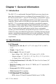
When you place the POC-175 upright on the desktop, its front panel
appears as shown in Figure 2-1.
Figure 2.1: Front View of the Point of Care Terminal
Volume adjustment
Power Indicator LED (Green- Power ON)
Brightness adjustment