PPC-120/140 Pentium® MMX processor-based panel PC with 12.1"/13.
Copyright Notice This document is copyrighted, 1998, by Advantech Co. Ltd. All rights are reserved. Advantech Co., Ltd. reserves the right to alter the products described in this manual at any time without notice. No part of this manual may be reproduced, copied, translated or transmitted in any form or by any means without the prior written permission of Advantech. Information provided in this manual is intended to be accurate and reliable.
FCC Class B This equipment has been tested and found to comply with the limits for a Class B digital device, pursuant to Part 15 of the FCC Rules. These limits are designed to provide reasonable protection against harmful interference when the equipment is operated in a residential environment. This equipment generates, uses and can radiate radio frequency energy. If not installed and used in accordance with this user's manual, it may cause harmful interference to radio communications.
Packing List Before installing your panel PC, ensure that the following materials have been received: • • • PPC-120/140 series panel PC User's manual Accessories for PPC-120/140 - Y-shaped adapter for PS/2 mouse and AT keyboard - Power cord (1.
Additional Information and Assistance 1. Visit the Advantech Web sites at www.advantech.com or www.advantech.com.tw where you can find the latest information about the product. 2. Contact your distributor, sales representative, or Advantech's customer service center for technical support if you need additional assistance.
Safety Instructions 1. Read these safety instructions carefully. 2. Keep this User's Manual for later reference. 3. Disconnect this equipment from any AC outlet before cleaning. Use a damp cloth. Do not use liquid or spray detergents for cleaning. 4. For plug-in equipment, the power outlet socket must be located near the equipment and must be easily accessible. 5. Keep this equipment away from humidity. 6. Put this equipment on a reliable surface during installation.
Wichtige Sicherheishinweise 1. Bitte lesen sie Sich diese Hinweise sorgfältig durch. 2. Heben Sie diese Anleitung für den späteren Gebrauch auf. 3. Vor jedem Reinigen ist das Gerät vom Stromnetz zu trennen. Verwenden Sie Keine Flüssig-oder Aerosolreiniger. Am besten dient ein angefeuchtetes Tuch zur Reinigung. 4. Die NetzanschluBsteckdose soll nahe dem Gerät angebracht und leicht zugänglich sein. 5. Das Gerät ist vor Feuchtigkeit zu schützen. 6.
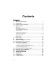
Contents Chapters 1 1.1 1.2 1.3 1.4 2 2.1 2.2 2.3 2.4 2.5 2.6 3 3.1 3.2 3.3 viii General Information 1 Introduction ...................................................................2 How to Use This Manual ...............................................4 Specifications ................................................................6 General ......................................................................................... 6 Standard PC functions ................................................
3.4 3.5 3.6 3.7 3.8 3.9 3.10 3.11 3.12 3.13 3.14 3.15 3.16 4 4.1 4.2 4.3 4.4 4.5 4.6 4.7 5 5.1 PCMCIA ......................................................................24 PS/2 Mouse and Keyboard .........................................27 PCI/ISA Bus Expansion ..............................................27 Parallel Port ................................................................29 Serial COM Ports ........................................................29 VGA Port................................
5.2 CPU Installation and Upgrading .................................49 5.2.1 System clock setting (JP11, JP8) ....................................... 49 5.2.2 CPU core voltage setting (JP13) ........................................ 51 5.2.3 CPU frequency ratio setting (JP14) .................................... 54 5.2.4 CMOS clear for external RTC (JP12) ................................. 56 5.2.5 Cyrix linear mode enable (JP10) ......................................... 56 5.2.6 Reset system (JP16) .........
8 Audio 87 8.1 Introduction .................................................................88 8.2 Installation of Audio Driver ..........................................88 8.2.1 Installation of MS-DOS ....................................................... 88 8.2.2 Changing settings in DOS .................................................. 89 8.2.3 Controlling volume in DOS ................................................. 90 8.2.4 Installation for WINDOWS 3.1 ............................................
10 Touchscreen 119 10.1 Introduction ...............................................................120 10.1.1 General information ....................................................... 120 10.1.2 Specifications ................................................................ 120 10.1.3 Environmental specifications ......................................... 120 10.2 Installation of Touchscreen Driver ............................121 10.2.1 Installation for MS-DOS and WINDOWS 3.1 ................. 122 10.2.
Appendices A B C D E E.1 E.2 E.3 E.4 LCD Specifications and Selection Settings 139 Programming the Watchdog Timer 141 Programming the Watchdog Timer ...........................142 Full Disassembly Procedures 145 Pin Assignments 153 IR Connector (J1) .....................................................154 Flat Panel Display Connector (J2) ............................155 Flat Panel Display Connector (J3) ............................156 Internal COM4 Connector (J4) ..................................
Tables Table 5-1: Jumpers and their functions ................................................... 45 Table 5-2: Panel PC connectors ............................................................. 47 Table 5-3: System/PCI clock setting (JP11) ........................................... 50 Table 5-4: PCI bus clock setting (JP8) .................................................... 51 Table 5-5: CPU voltage setting (JP13) ...................................................
Table A-1: PPC-120/140 series LCD specifications .............................. 140 Table D-1: IR Connector (J1) ................................................................ 154 Table D-2: Flat Panel Display Connector (J2) ....................................... 155 Table D-3: Flat Panel Display (J3) ........................................................ 156 Table D-4: Internal COM4 Connector (J4) ............................................ 156 Table D-5: Touchscreen Power Connector (J5) ............
Figures Figure 1-1: The panel PC in perspective ................................................... 3 Figure 1-2: How to read the PPC-120/140 manual ................................... 5 Figure 1-3: Dimensions of the PPC-120/140 .......................................... 10 Figure 2-1: Front view of the panel PC ................................................... 12 Figure 2-2: Left side view of the panel PC .............................................. 13 Figure 2-3: Rear view of the panel PC ............
Figure C-1: Steps 1 - 4 ......................................................................... 147 Figure C-2: Steps 5 - 6 ......................................................................... 149 Figure C-3: Steps 7 - 11 ....................................................................... 151 Figure E-1: Cutout dimensions of the PPC-120/140 ............................. 172 Figure E-2: Panel mounting ..................................................................
xviii
CHAPTER 1 General Information This chapter gives background information on the PPC-120/140 panel PC.
1.1 Introduction The PPC-120/140 panel PC is a multimedia Pentium® MMX processor-based computer that is designed to serve as a human machine interface (HMI) and as a desktop computer. It is a PC-based system with 12.1"/13.8" color TFT or STN LCD display, on-board PCI Ethernet controller, multi-COM port interfaces and a 16-bit audio controller. With built-in CD-ROM drive, floppy drive and PCMCIA expansion sockets, the PPC-120/140 is as compact and user-friendly as a notebook computer.
Touchscreen CRT Monitor Network Fax modem Speakers Printer Keyboard Joystick Mouse Figure 1-1:The panel PC in perspective Note: The illustrations of the panel PC in this manual may differ slightly from the appearance of the panel PC which you have bought. This is because the panel PC product series has two different LCD screen sizes: 12.1" and 13.8".
1.2 How to Use This Manual This manual contains all the information you need to set up and use the panel PC. In addition to this manual, you may also want to consult the manuals for your operating system, software applications and peripherals. Whether you are a new or an experienced user, you will benefit more from this manual if you are familiar with its organization. This manual is divided into ten chapters, plus five appendices.
Appendix E helps users install the panel PC, which is mountable in a variety of ways. If you are a commercial user and the panel PC unit you bought is a complete set with CPU, hard disk drive, SDRAM, CD-ROM drive, floppy disk drive and PCMCIA expansion slots included, you may only need to read Chapters 1 through 3 regarding hardware operation. For additional drivers and BIOS setup information, you should read Chapters 6 through 9.
1.3 Specifications General • Dimensions (W x H x D): 375 x 285 x 93.3 mm (14.7" x 11.2" x 3.7") • Weight: 5.2 kg (11.5 lbs) • Power supply: 80 watts Input voltage: 115 VAC / 3 A ~ 230VAC / 1.5A @ 47 ~ 63 Hz Output voltage: +5 V @ 12 A, +12 V @ 1 A • Cooling fan dimensions (L x W x H): 40 x 40 x 10 mm (1.6" x 1.6" x 0.4") • Disk drive housing: Space for one 2.5" HDD, one 12.7 mm compact CD-ROM drive, and one slim type 3.
• Serial ports: Four serial ports with three RS-232 ports (COM1, 3, and 4), one RS-232/422/485 port (COM2). All ports are compatible with 16C550 UARTs. • Universal serial bus (USB) port: Supports up to two USB ports • PCI/ISA bus expansion slot: Accepts either one ISA card or one PCI bus card • Infrared transceiver: IrDA 1.1, HP-SIR and Sharp ASK compatible with speeds up to 115.2 Kbps • Watchdog timer: 63-level, interval 1 ~ 63 seconds.
PCI bus Ethernet interface • Chipset: Realtek RTL 8139 PCI local bus Ethernet controller • Ethernet interface: Full compliance with IEEE 802.3u 100Base-T and 10 Base-T specifications.
Optional modules • CPU: Intel Pentium® 75 ~ 233 MHz with MMX, P55C/P54C, AMD K5, K6, Cyrix M1, M2 • Memory: 16/32/64/128 MB SDRAM • HDD: 2.5" HDD • Touchscreen: Analog resistive or analog capacitive • CD-ROM drive: Compact 24X CD-ROM or above • PCMCIA interface: Complies with 1995 PCMCIA card standard. Supports two PCMCIA card/CardBus slots. Two sockets support both a 16-bit PCMCIA card and a 32-bit CardBus simultaneously.
1.
CHAPTER 2 System Setup • A Quick Tour of the Panel PC • Preparing for First-time Usage • Running the Setup Program • Installing the System Software • Installing the Drivers
2.1 A Quick Tour of the Panel PC Before you start to set up the panel PC, take a moment to become familiar with the locations and purposes of the controls, drives, connectors and ports, which are illustrated in the figures below. When you place the panel PC upright on the desktop, its front panel appears as shown in Figure 2-1. The size of your panel PC's liquid crystal display (LCD) varies according to the model that you purchased.
When you look at the left side of the panel PC, you will see the floppy disk drive, CD-ROM drive and PCMCIA expansion sockets, as shown in Fig. 2-2.
When you turn the panel PC around and look at its rear cover, you will find the PCI/ISA expansion slot located on the left side. This slot is covered by a side panel cover. The sunken I/O section is at the bottom of the panel PC, as shown in Fig. 2-3. (The I/O section includes various I/O ports, including serial ports, parallel port, the Ethernet port, USB ports, the microphone jack, and so on.
Figure 2-4 shows the I/O section and power switch of the panel PC. Main power switch AC inlet Figure 2-4: Tilted rear view of the panel PC 2.2 Preparing For First-time Use Before you start to set up the panel PC system, you should have at least the following items ready: • Power cord (in the accessory box) • Y-shaped connector (in the accessory box) • AT keyboard • PS/2 or serial mouse (for system software installation i.e. Microsoft Windows, NT, etc.
2.3 Installation Procedures 2.3.1 Connecting the power cord The panel PC can only be powered by an AC electrical outlet (90 ~ 240 volts, 50 ~ 60 Hz). Be sure to always handle the power cords by holding the plug ends only. Follow these procedures in order: 1. Connect the female end of the power cord to the AC inlet of the panel PC. (See Fig. 2-5.) 2. Connect the 3-pin male plug of the power cord to an electrical outlet.
2.3.2 Connecting the keyboard and mouse 1. Connect the Y-shaped adapter to the PS/2 mouse and keyboard port on the I/O section of the panel PC. (See Fig. 2-6.) 2. Connect the PS/2 mouse and keyboard to the Y-shaped adapter. (See Fig. 2-6.) If you use a serial mouse and your panel PC has a touchscreen, you can connect the mouse to any COM port except COM4. Y-shaped adapter PS/2 mouse and keyboard port PS/2 mouse Keyboard Figure 2-6: Connecting the keyboard and mouse 2.3.
2.4 Running the BIOS Setup Program Your panel PC is likely to have been properly set up and configured by your dealer prior to delivery. You may still find it necessary to use the panel PC's BIOS (Basic Input-Output System) setup program to change system configuration information, such as the current date and time or your type of hard drive. The setup program is stored in read-only memory (ROM).
2.5 Installing System Software Recent releases of operating systems from major vendors include setup programs which load automatically and guide you through hard disk preparation and operating system installation. The guidelines below will help you determine the steps necessary to install your operating system on the panel PC hard drive. Note: Some distributors and system integrators may have already pre-installed system software prior to shipment of your panel PC.
To set up the CD-ROM function, insert the floppy disk with the CD-ROM drive driver into the floppy disk drive and type "install" after the following prompt is displayed on screen: A: > INSTALL Press "Enter", and the installation process will be completed in a few seconds. The standard procedures for installing the Ethernet, SVGA, audio, and touchscreen drivers are described in Chapters 6, 7, 8 and 10 respectively.
CHAPTER 3 Using the Panel PC • Floppy Drive • CD-ROM Drive • PCMCIA Sockets • PS/2 Mouse and Keyboard • Audio Interface • PCI/ISA Bus Expansion • Parallel Port • Serial COM Ports • VGA Port • Game Port • USB Ports • Audio Interface • Ethernet • Adjusting the LCD Contrast and Brightness (STN) • Infrared Module • Touchscreen (Optional)
3.1 Introduction This chapter describes basic features and procedures for using the panel PC. Topics covered include the floppy drive, CD-ROM drive, I/O ports, touchscreen, and so on. 3.2 Floppy Drive To insert a diskette, hold it with your left hand, between your thumb and your other fingers, and push it toward the drive. (See Fig. 3-1.) Slide the disk until it clicks into place. Note that new diskettes must be formatted by your operating system before you can use them for data storage.
3.3 CD-ROM Drive To insert a CD-ROM disc, press the eject button of the CD-ROM drive. The yellow activity light will flash and the front panel will come out a short distance. Using your fingertips, hold the top and bottom of the front panel and pull it outward to the very end. (See Fig 3-2.) Align the center hole of the CD-ROM disc with the center circle of the CD-ROM holding plate. Press the transparent ring around the center hole of the CD-ROM until you hear a click.
3.4 PCMCIA PCMCIA cards are inserted and ejected in much the same way as diskettes. To insert a PCMCIA card, align the card with the socket and slide the card into the socket until it locks into place. Note that some PCMCIA memory cards must be prepared by your operating system before you can use them for data storage. See your PCMCIA card manual for details. To eject a PCMCIA card, first ensure that the panel PC is not accessing the memory card or device.
Network USB keyboard PS/2 mouse Printer Figure 3-4: Using the I/O interface (upper level ports excluding COM ports) Chapter 3 Using the Panel PC 25
Headphones CD-ROM Microphone player Joystick CRT monitor Serial mouse Figure 3-5: Using the I/O interface (lower level ports and COM ports) 26 PPC-120/140 User's Manual
3.5 PS/2 Mouse and Keyboard If you wish to use a full-size desktop keyboard and PS/2 mouse with your panel PC, follow these instructions: 1. Be sure the panel PC is turned off. 2. Connect the Y-shaped adapter to the PS/2 mouse and keyboard port on the rear bottom side of the rear cover. (See Fig. 3-4 and Fig. 2-6.) 3. Attach the keyboard to the 5-pin port of the Y-shaped adapter. 4. Attach the PS/2 mouse to the 6-pin female PS/2 port of the Y-shaped adapter. 5. Turn on the panel PC. 3.
PCI/ISA expansion slot cover PCI/ISA bus card Metal plate Figure 3-6: PCI/ISA bus expansion 28 PPC-120/140 User's Manual
3.7 Parallel Port The panel PC supports the latest EPP and ECP parallel port protocols for improved performance and versatility with compatible printers or other devices. To connect the panel PC to a printer or other devices: 1. Be sure both the panel PC and the printer/devices are turned off. 2. Connect the 25-pin male connector of the printer cable to the 25-pin female port on the panel PC labelled "parallel port". 3.
3.9 VGA Port An external VGA-compatible device may be connected to the system through the 15-pin external port located on the rear of the system unit. The panel PC simultaneously supports an external CRT monitor in addition to its own LCD display. 1. Be sure the panel PC is turned off. 2. Connect the external monitor to the system. (See Fig. 3-5.) 3. Turn on the panel PC and the external monitor. 3.
3.12 Audio Interface The audio interface includes three jacks: microphone in, line out and line in. (See Fig. 3-5.) Their functions are: Microphone in: Use an external microphone to record voice and sound. Line out: Output audio to external devices such as speakers or earphones. The built-in speaker will not be disabled when the line out jack is connected to external audio devices. Line in: Input audio from an external CD player or radio. 1. Connect the audio device to the system. (See Fig. 3-5.) 2.
3.15 Infrared Module This sensor on the front panel supports the optional wireless transmitting and receiving of infra-red data. (See Fig. 2-1.) You must configure the setting through the BIOS setup (chipset features) to select whether UART2 is directed for use with COM2 or IrDA. 1. Place the panel PC and the infrared transceiving device (eg. printer) with their IrDA ports facing each other at the same horizontal level. The distance between the two IrDA ports should not exceed 1 meter (38"). 2.
CHAPTER 4 Hardware Installation and Upgrading • Overview of Hardware Installation and Upgrading • Disassembling the Panel PC • Installing the 2.
4.1 Overview of Hardware Installation and Upgrading The panel PC consists of a PC-based computer that is housed in a plastic rear panel and a shielding case. Your HDD, SDRAM, power supply, CPU, and so on are all readily accessible by removing the rear panel and shielding case. Any maintenance or hardware upgrades can be easily completed after removing the rear panel and shielding case.
4.2 Disassembling the Panel PC The following are standard procedures for disassembling the panel PC before you upgrade your system. All procedures are illustrated in Fig. 4-1. 1. Unscrew the seven screws that secure the rear cover, then remove the cover. 2. Unscrew the two screws of the PCI/ISA expansion PCB, and remove it. 3. Unscrew the four screws that secure the CPU cover. 4. Remove the floppy drive, HDD, and CD-ROM cables; then remove the side panel. 5.
Rear panel CPU cover PCI/ISA expansion PCB Side panel Figure 4-1: Disassembling the rear panel of the panel PC 36 PPC-120/140 User's Manual
4.3 Installing the 2.5" Hard Disk Drive (HDD) You can attach one enhanced Integrated Device Electronics (IDE) hard disk drive to the panel PC's internal controller which uses a PCI local-bus interface. The advanced IDE controller supports faster data transfer and allows the IDE hard drive to exceed 528 MB. The following are instructions for installation: 1. Detach and remove the rear cover and side panel. 2. There is a metal plate holding the HDD on the upper right-hand side of the shielding case. (See Fig.
4.4 Installing the Central Processing Unit (CPU) The panel PC's central processing unit (CPU) can be upgraded to improve system performance. The panel PC provides one 321-pin ZIF (Zero Insertion Force) socket (Socket 7) which is backward compatible with ZIF Socket 5 processors. The CPU must come with an attached heatsink and CPU fan to prevent overheating. The panel PC comes with one CPU fan with a unique connector in the accessory box.
10. Connect the power cable of the CPU fan to the 2-pin connector (J12). 11. After changing the CPU, you must set jumpers, including those for the PCI bus clock (JP8), system/PCI clock (JP11), frequency ratio (JP14), and voltage (JP13). (See Section 5.2.) 12. To remove the CPU, pull the lever out to the side a little and raise it as far as it will go. Lift out the CPU chip. NOTE! When you install a new CPU, be sure to adjust the board jumper settings. Improper settings may damage the CPU.
4.5 Installing the SDRAM Memory Module You can install from 16 MB to 128 MB of SDRAM memory. The panel PC system provides one 168-pin DIMM (Double Inline Memory Module) socket and supports 3.3 V SDRAM with a minimum speed of 12 ns. Note: The module can fit into the socket only one way. Pin 1 of the DIMM module must line up with the small arrowhead printed on the motherboard next to the DIMM socket. The golden pins of the module must point down into the DIMM socket. 1.
4.6 Installing the Floppy Disk Drive (FDD) Installation of a floppy disk drive is similar to that for a hard disk drive. The metal plate for holding the FDD is on the left side of the shielding case. The 26-pin yellow FPC cable is for connecting the FDD. Only 3.5" floppy disk drives (720 KB and 1.44 MB) can be attached to the metal plate. 1. Detach and remove the rear cover and side panel. 2. There is a metal plate for holding the FDD on the right side of the shielding case. (See Fig. 4-5.
4.7 Installing the CD-ROM Drive The compact CD-ROM drive used in the panel PC is not the common 5.25" CD-ROM drive seen in computer shops. It is the kind widely used in notebook computers. Install the CD-ROM drive as follows: 1. Detach and remove the rear cover, side panel and CPU cover. 2. Fasten the retaining clip on the CD-ROM drive with the two screws. 3. Slide the slim CD-ROM drive into the CD-ROM slot. (See Fig. 4-6.) 4. Attach the two screws on the side panel of the CD-ROM slot. 5.
CHAPTER 5 Jumper Settings and Connectors This chapter tells how to set up the panel PC hardware, including instructions on setting jumpers and connecting peripherals, switches and indicators. Be sure to read all the safety precautions before you begin the installation procedures.
5.1 Jumpers and Connectors 5.1.1 Setting jumpers You can configure your panel PC to match the needs of your application by setting jumpers. A jumper is the simplest kind of electrical switch. It consists of two metal pins and a small metal clip (often protected by a plastic cover) that slides over the pins to connect them. To “close” a jumper, you connect the pins with the clip. To “open” a jumper you remove the clip. Sometimes a jumper will have three pins, labeled 1, 2, and 3.
5.1.2 Jumpers The motherboard of the panel PC has a number of jumpers that allow you to configure your system to suit your applications. The table below lists the function of each of the board’s jumpers.
5.1.
5.1.4 Connectors On-board connectors link the panel PC to external devices such as hard disk drives or floppy drives. The table below lists the function of each of the board’s connectors.
5.1.
5.2 CPU Installation and Upgrading You can upgrade to a higher power Pentium®, AMD or Cyrix processor at any time. Simply remove the old CPU, install the new one, and set the jumpers for the new CPU type and speed. 5.2.1 System clock setting (JP11, JP8) JP11 and JP8 are used to set the CPU and PCI bus speeds respectively, to optimize the system's performance. The system chipset will sense the JP8 setting to get the bus frequency, then adjust its internal timing. JP11 is used to set the CPU and PCI clock.
Table 5-3: System/PCI clock setting (JP11) PCI clock 25 MHz CPU clock 50 MHz 1 30 MHz 60 MHz 1 33 MHz 66 MHz 1 28 MHz 55 MHz 1 38 MHz 75 MHz 1 42 MHz 83 MHz 1 (Reserved) 50 PPC-120/140 User's Manual
Table 5-4: PCI bus clock setting (JP8) PCI clock * CPUCLK/2 1 32MHz 1 * default setting 5.2.2 CPU core voltage setting (JP13) JP13 must be set to match the CPU type. The following chart shows the proper jumper settings for their respective VCC (CORE). (The VCC (I/O) for the CPU is fixed at 3.3 V.
Table 5-5: CPU voltage setting (JP13) VCC (CORE) 1.30 V VCC (CORE) 1.35 V V CC (CORE) 1.45 V 10 9 10 9 10 9 10 9 8 7 8 7 8 7 8 7 6 5 6 5 6 5 6 5 4 3 4 3 4 3 4 3 2 1 2 1 2 1 2 1 1.50 V 1.55 V 1.60 V 1.65 V 10 9 10 9 10 9 10 9 8 7 8 7 8 7 8 7 6 5 6 5 6 5 6 5 4 3 4 3 4 3 4 3 2 1 2 1 2 1 2 1 1.70 V 1.75 V 1.80 V 1.
VCC (CORE) NONE V CC (CORE) 2.10 V V CC (CORE) 2.20 V VCC (CORE) 2.30 V 10 9 10 9 10 9 10 9 8 7 8 7 8 7 8 7 6 5 6 5 6 5 6 5 4 3 4 3 4 3 4 3 2 1 2 1 2 1 2 1 2.40 V 2.50 V 2.60 V 2.70 V 10 9 10 9 10 9 10 9 8 7 8 7 8 7 8 7 6 5 6 5 6 5 6 5 4 3 4 3 4 3 4 3 2 1 2 1 2 1 2 1 2.80 V 2.90 V 3.00 V 3.
5.2.3 CPU frequency ratio setting (JP14) Table 5-6: CPU frequency ratio (for Intel) (JP14) P55C 3.5x 2x 3x 2.5x 54 P54C 1.5x 1 2 3 4 5 6 1 2 3 4 5 6 1 2 3 4 5 6 1 2 3 4 5 6 2x 3x 2.
Table 5-7: CPU frequency ratio (for AMD K6) (JP14) 2x 2.5x 1 2 1 2 3 4 3 4 5 6 5 6 1 2 1 2 3 4 3 4 5 6 5 6 1 2 1 2 3 4 3 4 5 6 5 6 1 2 1 2 3 4 3 4 5 6 5 6 3x 3.5x 4x 4.5x 5x 5.
5.2.4 CMOS clear for external RTC (JP12) Warning: To avoid damaging the computer, always turn off the power supply before setting “Clear CMOS”. Set the jumper back to “3.0 V Battery On” before turning on the power supply. Table 5-8: Clear CMOS/External RTC (JP12) * normal operation Clear CMOS 1 2 3 1 2 3 * default setting 5.2.5 Cyrix linear mode enable (JP10) The panel PC supports Cyrix M1 CPU with its linear access mode on L2 cache. This mode is set through JP10.
5.2.
5.3 COM-port Interface The panel PC provides four serial ports (COM1, 3, 4: RS-232; COM2: RS-232/422/485) in one COM port connector. 5.3.1 COM2 RS-232/422/485 setting (JP3, JP4, JP5) COM2 can be configured to operate in RS-232, RS-422, or RS-485 mode. This is done via JP6 and JP5.
COM1 and COM2 are one set. You can exchange the address range and interrupt IRQ of COM1 for the address range and interrupt IRQ of COM2. After exchanging, COM1's address range is 2F8 ~ 2FF and its request IRQ is IRQ3: and COM2's address range is 3F8 ~ 3FF and its interrupt IRQ is IRQ4. COM3 and COM4 are another set. Their selectable function is the same as the COM1/COM2 set.
5.4 VGA Interface The panel PC's’s PCI SVGA interface can drive conventional CRT displays and is capable of driving a wide range of flat panel displays, including electroluminescent (EL), gas plasma, passive LCD and active LCD displays. The board has two connectors to support these displays simultaneously; one for standard CRT VGA monitors and one for flat panel displays. CRT display port information can be found in Section 3.9 - VGA Port.
5.4.2 Panel type select (JP9) Table 5-17: Panel type select (JP9) Maximum Resolution 1. 1024 x 768 Display Type DSTN color Maximum Resolution 2. 1280 x 1024 Display Type TFT color 7 8 7 8 5 6 5 6 3 4 3 4 1 2 1 2 3. 640 x 480 DSTN color 4. 800 x 600 DSTN color 7 8 7 8 5 6 5 6 3 4 3 4 1 2 1 2 5. 640 x 480 SHARP TFT color 6. 640 x 480 18-bit TFT color 7 8 7 8 5 6 5 6 3 4 3 4 1 2 1 2 7. 1024 x 768 TFT color 8.
Maximum Resolution 9. 800 x 600 Display Type TFT color (44 K BIOS only) 8 7 8 5 6 5 6 3 4 3 4 1 2 1 2 DSTN color (44 K BIOS only) 12. 800 x 600 DSTN color 7 8 7 8 5 6 5 6 3 4 3 4 1 2 1 2 13.1024 x 768 TFT color (44 K BIOS only) 14. 1280 x 1024 DSTN color (44 K BIOS only) 7 8 7 8 5 6 5 6 3 4 3 4 1 2 1 2 15. 1024 x 600 PPC-120/140 Display Type TFT color 7 11. 800 x 600 62 Maximum Resolution 10. 800 x 600 TFT color (48•K BIOS only) 16.
5.5 Watchdog Timer Configuration An on-board watchdog timer reduces the chance of disruptions which EMP (electromagnetic pulse) interference can cause. This is an invaluable protective device for standalone or unmanned applications. Setup involves one jumper and running the control software. (Refer to Appendix B.) 5.5.1 Watchdog activity selection (JP15) When the watchdog timer activates (i.e. CPU processing has come to a halt), it can reset the system or generate an interrupt on IRQ11.
64 PPC-120/140 User's Manual
CHAPTER 6 PCI Bus Ethernet Interface This chapter provides information on Ethernet configuration. • Introduction • Installation of Ethernet Driver - • Installation for MS-DOS & WINDOWS 3.
6.1 Introduction The PPC-120/140 is equipped with a high performance 32-bit Ethernet chipset which is fully compliant with IEEE 802.3 100 Mbps CSMA/CD standards. It is supported by major network operating systems. It is also both 100Base-T and 10Base-T compatible. The medium type can be configured via the RSET8139.exe program included on the utility disk. The Ethernet port provides a standard RJ-45 jack.
6.2.1 Installation for MS-DOS & WINDOWS 3.1 If you want to set up your Ethernet connection under the MS-DOS or Windows 3.1 environment, you should first check your server system model. For example, MS-NT, IBM-LAN server, and so on. Then choose the correct driver to install in your panel PC. The installation procedures for various servers can be found in the directory path "LAN/TXT/*" of the drivers and utilities CD-ROM, where * is your server model.
6.2.2 Installation for WINDOWS 95 68 1. a. Select "Start", "Settings", "Control Panel". b. Double click "Network". 2. a. Click "Add" and prepare to install network functions. 3. a. Select the "Adapter" item to add the Ethernet card. 4. a. Click "Have Disk" to install the driver.
5. a. Insert the disc into the CD-ROM drive. b. Fill in the correct path. c. Click "OK". D:\Lan\ 6. a. Choose the "Realtek" item. b. Click "OK". 7. a. Make sure the configurations of relative items are set correctly. b. Click "OK" to reboot.
6.2.3 Installation for WINDOWS NT 1. a. Select "Start", "Settings", "Control Panel". b. Double click "Network". 2. a. Choose the "Adapters" label. b. Click the "Add" button. 3. a. Press "Have Disk". 4. a. Type "D:". b. Press "OK".
5. a. Insert the disc into the CD-ROM drive. b. Fill in the correct path. c. Press the "OK" button. 6. a. Choose the "Realtek" item. b. Press the "OK" button. 7. a. Make sure the configurations of relative items are set correctly. b. Press the "OK" button to reboot.
6.3 Further Information Realtek web: www.realtek.com Advantech web: www.advantech-usa.com or www.advantech.com.
CHAPTER 7 PCI SVGA Setup • Introduction • Installation of SVGA Driver - • Installation for WINDOWS 3.
7.1 Introduction The PPC-120/140 has an on-board PCI flat panel/VGA interface. The specifications and features are described as follows: Chipset The PPC-120/140 uses a C&T 65555 chipset for its PCI/SVGA controller. It supports many popular LCD, EL, and gas plasma flat panel displays and conventional analog CRT monitors. The 65555 VGA BIOS supports monochrome LCD, EL, color TFT and STN LCD flat panel displays.
7.2 Installation of SVGA driver Complete the following steps to install the SVGA driver. Follow the procedures in the flow chart that apply to the operating system that you you are using within your PPC-120/140. Important: 1. The following windows illustrations are examples only. You must follow the flow chart instructions and pay attention to the instructions which then appear on your screen. 2.
7.2.1 Installation for Windows 3.1 76 1. a. Insert the disc into the CD-ROM drive. b. Select "File" in Program Manager. c. Click "Run" and type: "D:\VGA\ Win31\Setup.exe". 2. a. C h o o s e t h e language you want to use during installation. 3. a. Select the highlighted item. b. P r e s s " E N T E R " . 4. a. Press "ENTER" to install all resolutions. PPC-120/140 User's Manual D:\VGA\Win31\Setup.
5. a. Type the path of the operating system. 6. a. When installation is completed, reboot the system. b. You will see the "ChipsCPL" icon in the control panel. ChipsCPL 7. a. Double click "ChipsCPL". b. Adjust screen size, color and refresh rate to your preferences.
7.2.2 Installation for Windows 95 78 1. a. Select "Start", "Settings", "Control Panel", "Display", "Settings". b. Press "Advanced Properties". 2. a. Choose the "Adapter" label. b. Press the "Change..." button. 3. a. Press the "Have Disk" button. 4. a. Insert the disc into the CD-ROM drive. b. T y p e "D:\VGA\Win95\". c. Press "OK".
5. a. Select the highlighted item. b. Click the "OK" button. 6. a. C & T 6 5 5 5 5 appears in the adapter label. b. Click the "Apply" button. 7. a. Press "Yes" to reboot. 8. a. Repeat Step 1 on the previous page of this manual. The "CHIPS" label appears in "Display". b. Adjust resolution and color.
a. Click the "CHIPS" label. b. Adjust the refresh [7] rate and display type. c. Press "OK" to exit. 9. 10. a. Press "Yes" to set the monitor type. 11. a. Select "Standard", "Super VGA 800 x 600", or "XGA". b. Press the "OK" button. 12. a. Choose "Restart" to reboot.
7.2.3 Installation for Windows NT 1. a. Select "Start", "Settings", "Control Panel". b. Double click the "Display" icon. 2. a. Choose the "Settings" label. b. Press the "Display Type" button. 3. a. Press the "Change..." button. 4. a. Click the "Have Disk..." button.
5. a. Insert the disc into the CD-ROM drive. b. Type "D:\VGA\NT40\" in the blank. c. Press the "OK" button. D:\VGA\NT40\ 82 6. a. Select the highlighted item. b. Press the "OK" button. 7. a. Press "Yes" to proceed. 8. a. Press "OK" to reboot.
9. a. Repeat Step 1 in this manual, to select the "Settings" label. b. Adjust resolution and color. c. Click "Test" to see the result. d. Click "OK" to save the setting.
7.2.4 Installation for OS/2 84 1. a. Select "OS/2 System", "Command Prompts", "OS/2 Window". b. Insert the disc into the CD-ROM drive. c. Type "D: ", . d. Type "setup D:C:", and press . 2. a. Press "OK" to shut down. 3. a. Reboot again, by selecting "OS/2 System", "System Setup", "Display Driver Install". 4. a. Enable "Primary Display". b. Click the "OK" button.
5. a. Press "OK" one more time. 6. a. Type "D:\" in the blank. b. Click the "Install..." button. 7. a. Press "OK" to shut down and restart. 8. a. Select "OS/2 System", "System Setup", "System".
9. a. Select the "Screen" tab. b. Change resolution and refresh rate. END 7.3 Further Information For further information about the PCI/SVGA installation in your PPC-120/140, including driver updates, troubleshooting guides and FAQ lists, visit the following web resources: C&T web site: www.chips.com Advantech web sites: www.advantech.com www.advantech.com.
CHAPTER 8 Audio • Introduction • Installation of Audio Driver - Installation for MS-DOS & WINDOWS 3.
8.1 Introduction The PPC-120/140 on-board audio interface provides high-quality stereo sound and FM music synthesis (ESFM) by using the ES1869 audio controller from ESS Technology, Inc. The audio interface can record, compress, and play back voice, sound, and music with a built-in mixer control. The PPC-120/140 on board audio interface also supports the Plug and Play (PnP) standard and provides PnP configuration for audio, FM, and MPU-104 logical devices.
8.2.2 Changing settings in DOS The audio controller settings can be changed in the DOS environment by using the DOS SETUP utility located in the UTILITY subdirectory of the CD-ROM. To change the settings, simply type DOSSET at the DOS prompt. Follow the instructions on screen to choose the new settings for the ES1869 audio controller.
8.2.3 Controlling volume in DOS The ES1869 audio controller provides software control of the settings for audio volumes. The VOLUME CONTROL utility located in the UTILITY\Audio\ subdirectory of the CD-ROM is used to control the volume settings in DOS. To control the volume settings, simply type "ESSVOL" at the DOS prompt with appropriate parameters.
8.2.4 Installation for WINDOWS 3.1 Note: The following windows illustrations are examples only. You must follow the flow chart instructions and pay attention to the instructions which then appear on your screen. 1. a. Insert the disc into the CD-ROM drive. b. Select "File" in "Program Manager" and click "Run". c. Type "D:\Audio\win31\ setup.exe". 2. a. Click "Continue" to install. 3. a. Click "Driver Installation". 4. a. Relative settings will be added in "autoexec.bat". b.
8.2.5 Installation for WINDOWS 95 92 1. a. Select "Start", "Settings", "Control Panel", "System", "Device Manager". b. Click the "Other Devices" item. c. Remove items related to ESS 1869. 2. a. Select "Add new hardware". b. Click "Next". 3. a. Choose "No", click "Next". 4. a. Select "Sound, video...". b. Click "Next".
5. a. Click "Have Disk". 6. a. Insert the disc into the CD-ROM drive. b. Type the correct path "D:\Audio\win95" and click the "OK" button. 7. a. Select "ES1869 Control interface". 8. a. Click "Finish" to complete.
9. a. Click "OK". 10. a. Insert Windows 95 CD. b. Type the path of your Windows 95 disc and click "OK". 11. a. Click "Yes" to restart.
8.2.6 Installation for WINDOWS NT 1. a. Select "Start", "Settings", "Control Panel". b. Double click "Multimedia". 2. a. Select the "Devices" item. b. Click "Add". 3. a. Select the "Unlisted..." item. b. Click "OK". 4. a. Insert the disc into the CD-ROM drive. b. Type "D:\Audio\nt40" and click "OK".
5. a. Choose the highlighted item. b. Click the "OK" button. 6. a. Set the I/O address. b. Click "Continue". 7. a. Set ESS 1869 configuration. b. Click "OK" to restart.
CHAPTER 9 Award BIOS Setup This chapter describes how to set BIOS configuration data.
9.1 Award BIOS Setup The PPC-120/140 comes with an Award BIOS chip that contains the ROM setup for your system. This chip serves as an interface between the processor and the rest of the mainboard's components. This chapter explains the information contained in the setup program and tells you how to modify the settings according to your system configuration. Some setup items will not be explained, because it is recommended that users do not change such items.
A setup program, built into the system BIOS, is stored in the CMOS RAM that allows the configuration settings to be changed. This program is executed when the user changes the system configuration; when the user changes the system backup battery; or when the system detects a configuration error and asks the user to run the setup program. At power-on RAM testing, the message "Press DEL to enter Setup" appears. After pressing the "DEL" key, the CMOS setup utility screen will appear as shown in Fig. 9-1.
9.3.1 Hard Disk Configurations TYPE: Select from 1 to 45 to fill the remaining fields with predefined values for disk drives. Select "User" to fill the remaining fields. Select "Auto" to detect the HDD type automatically. SIZE: Hard disk size. The unit is megabytes (MB). CYLS: The cylinder number of the hard disk. HEAD: The read/write head number of the hard disk. PRECOMP: The cylinder number at which the disk drive changes the write timing.
9.4 BIOS Features Setup Figure 9-3: BIOS features setup screen Moving around the BIOS Features and Chipset Features setup programs works the same way as moving around the Standard CMOS setup program. (Refer to the next section for Chipset Features setup.) The BIOS Features setup program is shown above. Users are not encouraged to run the BIOS and Chipset Features setup programs. Your system should have been fine-tuned before shipping.
External Cache When enabled, supports an external cache SRAM. The options are: Enabled (Default), Disabled. Quick Power On Self Test When enabled, allows the BIOS to bypass the extensive memory test. The options are: Disabled (Default), Enabled. Boot Sequence Allows the system BIOS to first try to boot the operating system from the selected disk drive. The options are: A, C (Default); C (only); C, CDROM, A; CDROM, C, A.
Typematic Rate (Chars/Sec) Sets the rate of a character repeat when the key is held down. The options are: 6 (Default), 8, 10, 12, 15, 20, 24, 30. Typematic Delay (msec) Sets the delay time before a character is repeated. The options are: 250 (Default), 500, 750, 1000 milliseconds. Security Option Allows you to set the security level of the system. The options are: Setup (Default), System. PCI/VGA Palette Snoop When enabled, allows you to install an enhanced graphics adapter card.
9.5 Chipset Features Setup Note: It is strongly recommended that setup items in this section NOT be changed, because advanced knowledge is required to effect such changes. Figure 9-4: Chipset features setup screen System BIOS Cacheable When enabled, allows the ROM area FOOOH-FFFFH to be cacheable when the cache controller is activated. The recommended setting is "Disabled", especially for high speed CPUs (200 MHz and above).
Memory Hole at 15M-16M When enabled, the memory hole at the 15 MB address will be relocated to the 15 ~ 16 MB address range of the ISA cycle when the processor accesses the 15 ~ 16 MB address area. When disabled, the memory hole at the 15 MB address will be treated as a DRAM cycle when the processor accesses the 15 ~ 16 MB address. The options are: Disabled (Default), Enabled. 9.
PM Control by APM The option "No" allows the BIOS to ignore the APM (Advanced Power Management) specification. Selecting "Yes" will allow the BIOS to wait for APM's prompt before it enters Doze mode, Standby mode, or Suspend mode. If the APM is installed, it will prompt the BIOS to set the system into power saving mode after all tasks are done. The options are: Yes (Default), No. Video Off Option This feature provides the selections for the video display power saving mode.
Hot Key Power Off This function is designated as "Disabled". HDD Off After Selecting "Disabled" will turn off the hard disk drive (HDD) motor. Selecting "1 Min.. 15 Min" allows you to define the HDD idle time before the HDD enters Power Saving Mode. The options "1 Min.. 15 Min" and "When Suspend" will not work concurrently. When the HDD is in Power Saving Mode, any access to the HDD will wake it up. The options are: Disabled (Default), 1 Min.. 15 Min.
HDD Ports Activity Selecting "Enabled" will enable the power management timer when a no activity event is detected in the hard disk drive. Selecting "Disabled" will disable the PM timer even if a no activity event is detected. The options are: Enabled (Default), Disabled. VGA Activity Selecting "Enabled" will enable the power management timer when a no activity event is detected in the VGA. Selecting "Disabled" will disable the PM timer even if a no activity event is detected.
Note: Under certain operating systems such as Windoes NT 4.0 (Build 1381), the CD auto-insertion feature might have some effect on power management. It is recommended that the CD-ROM drive use the secondary channel, and that the following Power Management Setup features be set: HDD & FDD: Off IRQ15 (Reserved): Secondary 9.7 PNP/PCI Configuration Setup Figure 9-6: PNP/PCI configuration setup screen Resources Controlled By If set at "Auto", the BIOS automatically arranges all system resources for you.
Reset Configuration Data When enabled, this feature allows the system to clear the last BIOS configuration data and then reset the data with the default BIOS configuration data. The options are: Disabled (Default), Enabled. PCI IRQ Activated By If your IDE card is triggered by edge, set it at "Edge". The options are: Level (Default), Edge. PCI IDE 2nd Channel This item allows you to designate an IDE controller board inserted into one of the PCI slots as your secondary IDE controller.
9.8 Load BIOS Defaults Figure 9-7: Load BIOS defaults screen The BIOS defaults screen contains the most appropriate values of the system parameters that allow minimum system performance. 9.9 Load Setup Defaults Selecting this field loads the factory defaults for BIOS and Chipset Features. The system will automatically detect these defaults.
9.10 Integrated Peripherals WDT Active When Power ON 63 sec Figure 9-8: Integrated peripherals screen Internal PCI/IDE When you select "Both", two PCI/IDE ports will be enabled. If you select "Disabled", both PCI/IDE ports will be enabled. You can also select one of two ports to be enabled by selecting "Primary" or "Secondary". The options are: Both (Default), Disabled, Primary, Secondary. IDE Primary/Secondary Master/Slave PIO IDE hard disk drive controllers can support up to separate hard drives.
PIO means Programmed Input/Output. Rather than having the BIOS issue a series of commands to effect a transfer to or from the disk drive, PIO allows the BIOS to tell the controller what it wants and then let the controller and the CPU perform the task by themselves. Your system supports five modes, numbered from 0 through 4, which differ primarily in timing. When "Auto" is selected, the BIOS will choose the best available mode. The options are: Auto, (Default), Disabled.
WDT Active When Power ON This is Advantech's patented watchdog function which can reboot the system should the computer hang in the BIOS checkup. The options are: 63 sec (Default), Disabled, 31 sec, 15 sec. Onboard Serial Ports 1 & 2 If the serial ports use the onboard I/O controller, you can modify your serial port parameters. The options for Port 1 are: 3F8/IRQ4 (Default), 2E8/IRQ3, Disabled, 2F8/IRQ3, 3E8/IRQ4. The options for Port 2 are: 2F8/IRQ3 (Default), 3E8/IRQ4, 2E8/IRQ3, Disabled, 3F8/IRQ4.
ECP Mode Use DMA You can choose different DMA modes for data transfer. The options are: 3 (Default), 1. PS/2 mouse function When enabled, the PS/2 mouse is activated. The options are: Disabled (Default), Enabled. USB Controller When enabled, the USB devices are activated. The options are: Disabled (Default), Enabled. Ethernet Boot ROM When enabled, your system will be able to boot up through the Ethernet. The options are: Disabled (Default), Enabled.
9.12 IDE HDD Auto Detection ROM PCI/ISA BIOS (2A5IIAKA) IDE HDD AUTO DETECTION AWARD SOFTWARE, INC. HARD DISK TYPE SIZE CYLS. HEADS PRECOMP DRIVE C: (MB) 790 15 65535 LANDZ SECTORS 789 SELECT SECONDARY SLAVE OPTION (N=Skip): N MODE 57 . Note: Some OSs (such as SCO-UNIX) must use “NORMAL” for installation Figure 9-9: IDE HDD auto detection screen The IDE Hard Disk Drive Auto Detection feature automatically configures your new hard disk. Use it for quick configuration of new hard disk drives.
9.13 Save and Exit Setup Figure 9-10: Save and exit setup screen After you have made changes in the BIOS setup, press "Esc" to return to the main menu. Move the cursor to "Save and Exit Setup", or press "F10" and then press "Y", to change the CMOS Setup. If you did not change anything, press "Esc" again or move the cursor to "Exit Without Saving" and press "Y" to retain the setup settings.
118 PPC-120/140 User's Manual
CHAPTER 10 Touchscreen • Introduction • Installation of Touchscreen Driver - Installation for MS-DOS & WINDOWS 3.
10.1 Introduction 10.1.1 General information The PPC-120/140's optional touchscreen incorporates advanced second-generation 5-wire resistive technology. It allows 75% light transmission and has an antiglare surface. This produces greatly enhanced visual resolution. It also has a newly improved scratch-resistant hard coating. The touchscreen is manufactured from UL-recognized components (file no. E133802). When properly installed, the touchscreen's ball impact resistance meets the UL 1950 standard.
Chemical Resistance: The active area of the touchscreen is resistant to the following chemicals when exposed for a period of one hour at a temperature of 21° C (71° F): - Acetone - Methylene chloride - Methyl ethyl ketone - Isopropyl alcohol - Hexane - Ammonia-based glass cleaners - Turpentine - Mineral spirits - Foods and beverages 10.
10.2.1 Installation for MS-DOS and WINDOWS 3.1 1. a. Execute "install.exe" in the DOS environment. b. Press to continue. 2. a. Type the installing path of the ELO directory. 3. a. Select "Dos.." or "Windows..". Windows 3.1 a. Follow the on-screen instructions. 4. DOS Windows 3.1 5. 122 a. Choose the "Serial" item.
6. a. Select the "COM4" item. 7. a. Press to install. 8. a. Set serial port IRQ to 5. Windows 3.1 a. Type the Windows 3.1 path. 9. DOS Windows 3.1 10. a. Add "nomouse.com" to "autoexec.bat" if there is no mouse driver installed. b. If yes, the window disappears.
11. a. Press to continue. 12. a. Choose "Overwrite...". Windows 3.1 a. Press to continue. 13. DOS 14. Windows 3.1 a. Choose "Overwrite...". Windows 3.1 15. 124 a. Type "go" to run calibration. b. Touch fix points to calibrate.
16. a. Add -M6 behind monmouse in "autoexec.bat" to add "drag".
10.2.2 Installation for WINDOWS 95 If you want to use the touchscreen driver CD-ROM accompanying your panel PC, refer to the following flow chart instructions. 126 Note: An alternative Windows 95 touchscreen driver is available. The touchscreen supplier, Elo TouchSystems Inc., has recently revised its Windows 95 touchscreen driver to support selection of four COM ports. This new feature enables users to set up the touchscreen driver without going through a long register-changing process.
1. a. Insert the "Drivers and Utilities" CD-ROM. b. Select "Start", "Run". c. Type the path. eg. "D:\Elotouch\ monmouse\win95\ setup.exe" 2. a. Press the "Next" button. 3. a. Set the path of the directory. 4. a. Choose "Typical". D:\Elotouch\monmouse\win95\setup.
5. a. Click "OK" to upgrade the driver. 6. a. Click "OK" to make a backup copy. 7. a. Click "OK" to start the wizard. 8. a. Choose the COM port which is not used by other devices. b. Click "OK".
9. a. Click "OK" but do not reboot. 10. a. Select "Start" —› "Run". b. Type "regedit" in the blank. 11. a. From the left window, select: "Hkey_Local_Machine", "System", "CurrentControlSet", "Services", "VxD", "Monmouse", "TouchScreen00". 12. a.
13. a. Exit and reboot. b. Select "Start", "Settings", "Control Panel". c. Double click "Elo touchscreen". 14. a. Click "Calibrate".
10.2.3 Installation for WINDOWS NT 1. a. Insert the "Drivers and Utilities" CD-ROM. b. Select "Start", "Run". c. Type the path. eg. "D:\Elotouch\ monmouse\win95\ setup.exe" 2. a. Press the "Next" button. 3. a. Set the directory path. 4. a. Choose "Typical". D:\Elotouch\monmouse\winnt\setup.
5. a. Choose the COM port which is not used by other devices. b. Click "OK". 6. a. Click "OK" but do not reboot. 7. a. Click on the "My Computer" icon, and navigate to: "C":\winnt\system32\regedt32. 8. a. From the left window, select: "Hkey_Local_Machine" "System", "CurrentControlSet", "Services", "Monmouse", "Parameters".
9. a. Modify the items in right window: ComPort —› 4 ControllerAddress —› 2e8 ControllerLevel —› 5 ControllerVector —› 5 b. Click "OK" to save the settings. 10. a. Exit and reboot. b. Select "Start", "Settings", "Control Panel". c. Double click "Elo touchscreen". 11. a. Click "Calibrate". 12. a. Test the calibration.
10.2.4 Installation for OS/2 (MonitorMouse) BEFORE YOU BEGIN First be sure OS/2 is installed and operating properly with your mouse. As you will be modifying the CONFIG.SYS file, it is best to have the OS/2 installation disks or a bootable DOS disk readily available. This way, any problems in CONFIG.SYS which cause the system not to boot can be corrected by rebooting from the disk(s).
STEP 2 - COPY THE SOFTWARE The following files are on the MonitorMouse for OS/2 disk: !READ.ME! Text file containing any additions or changes made after this manual was printed. MONMOU01.SYS Touchscreen driver for serial touchscreen controllers on PC bus systems. MONMOU02.SYS Touchscreen driver for serial touchscreen controllers on Micro Channel systems. MONMOU03.SYS Touchscreen driver for PC bus and Micro Channel touchscreen controllers. ELOCAL2.
STEP 3 - MODIFY CONFIG.SYS MonitorMouse for OS/2 is installed by commands in CONFIG.SYS. Use your system editor to make these changes. In general, the changes are as follows: 1. Comment-out the existing DEVICE command(s) for your mouse. 2. Add a DEVICE command for the appropriate MonitorMouse for the OS/2 touchscreen driver immediately after the commented-out DEVICE commands(s). 3. Add a new DEVICE command for MOUSE.SYS. The order of the DEVICE commands is important.
Example MonitorMouse for OS/2 DEVICE command: Device=c:\elo\monmou01.sys 2210,1,9600 No Mouse If you do not wish to have a mouse connected, change the “stype=elomou$” flag to “type=elomou$” on the DEVICE=MOUSE.SYS command. Disabling the COM Drivers If your system COM ports are being used by the touchscreen and mouse, REM out the DEVICE=COM.SYS and DEVICE=VCOM.SYS commands (if present) in CONFIG.SYS. This prevents the COM drivers from displaying amessage saying the COM port is unavailable.
STEP 4 - INSTALL THE TOUCHSCREEN CONTROL PANEL The touchscreen control panel software program, ELOCAL2.EXE, is a presentation manager application for calibrating the touchscreen and setting various options. Add the \ELO\ELOCAL2.EXE program to the System Setup folder and label the icon “Touchscreen”. This is accomplished as follows: 1. Open the OS/2 System folder, then System Setup. 2. Open the Templates folder. 3. Drag the Program template with the right mouse button into the System Setup folder.
APPENDIX A LCD Specifications and Selection Settings Appendix A LCD Specifications and Selection Settings 138
Table A-1: PPC-120/140 series LCD specifications PPC-140T PPC-140S PPC-120T Display type (LCD) 13.8" TFT 13.8" DSTN 12.1" TFT Max. resolution 1024 x 768 1024 x 768 800 x 600 256 K colors 256 K colors 256 K colors 0.33 x 0.33 0.33 x 0.33 0.33 x 0.
APPENDIX B Programming the Watchdog Timer The PPC-120/140 is equipped with a watchdog timer that resets the CPU or generates an interrupt if processing comes to a standstill for any reason. This feature ensures system reliability in industrial standalone or unmanned environments.
Programming the Watchdog Timer To program the watchdog timer, you must write a program which writes I/O port address 443 (hex). The output data is a time interval value. The value range is from 01 (hex) to 3F (hex), and the related time interval is from 1 sec. to 63 sec. Data Time Interval 01 1 sec. 02 2 sec. 03 3 sec. 04 4 sec. • • • • • • 3F 63 sec. After data entry, your program must refresh the watchdog timer by rewriting the I/O port 443 (hex) while simultaneously setting it.
The following example shows how you might program the watchdog timer in BASIC: 10 20 30 40 50 60 70 80 REM Watchdog timer example program OUT &H443, data REM Start and restart the watchdog GOSUB 1000 REM Your application task #1, OUT &H443, data REM Reset the timer GOSUB 2000 REM Your application task #2, OUT &H443, data REM Reset the timer X=INP (&H443) REM, Disable the watchdog timer END 1000 • • • 1070 2000 • • • 2090 REM Subroutine #1, your application task • • • RETURN REM Subroutine #2, your applic
144 PPC-120/140 User's Manual
APPENDIX Full Disassembly Procedures C
If you want to completely disassemble the panel PC, follow the step-by-step procedures below. Users should be aware that Advantech Co., Ltd. takes no responsibility whatsoever for any problems or damage caused by the user’s disassembly of the panel PC. Make sure the power cord of the panel PC is unplugged before you start disassembly. The following procedures do not include the detailed disassembly procedures for the CPU, HDD, CD-ROM drive, FDD, and SRAM; all of which can be found in Chapter 4. 1.
Step 1 & Step 2 Step 4 Step 3 Figure C-1: Steps 1 - 4 Appendix C Full Disassembly Procedures 147
5. Unscrew the fourteen screws of the I/O bracket with a hexagonal screwdriver. The EMI protection cover lies below the I/O bracket. You can now remove both the bracket and the cover from the I/O ports. 6. Detach the flat cables of the speakers, LCD inverter, touchscreen and LCD from the motherboard. You can remove the motherboard from the LCD holding plate.
Step 5 I/O bracket EMI protection cover Step 6 Motherboard Figure C-2: Steps 5 - 6 Appendix C Full Disassembly Procedures 149
7. Unscrew the four screws on the power supply board. The power supply board can be detached from the LCD holding plate after unplugging the two cables from the power inlet and motherboard. 8. Detach the LCD holding plate and LCD by unscrewing the four screws at the bottom. The LCD inverter can also be detached by unscrewing the three screws at the bottom. 9. Detach the cables of the LCD, touchscreen, LCD inverter and speaker from the holes of the holding plate. 10.
Power supply Step 7 Step 8 Backplane plate Step 9 LCD Step 10 Touchscreen Step 11 Front panel Figure C-3: Steps 7 - 11 Appendix C Full Disassembly Procedures 151
152 PPC-120/140 User’s Manual
APPENDIX Pin Assignments D • IR Connector (J1) • Flat Panel Display Connector (J2) • Flat Panel Display Connector (J3) • Internal COM4 Connector (J4) • Touchscreen Power Connector (J5) • Sandisk SSD Connector (J6) • EIDE Hard Disk Drive Connector (J7) • Floppy Drive Connector (J8) • CD-ROM Connector (J9) • CPU Fan Power Connector (J10) • PCI/ISA Bus Expansion Connector (J11) • Fan Power Connector (J12) • AT Power Connector (J13) • ATX Power Connector (J14) (Reserved) • Intern
IR Connector (J1) 1 Table D-1: IR Connector (J1) Pin 1 2 3 4 5 154 Signal V CC Mode_Select IR_IN GND IR_out PPC-120/140 User’s Manual 2 3 4 5
Flat Panel Display Connector (J2) Table D-2: Flat Panel Display Connector (J2) Pin 1 3 5 7 9 11 13 15 17 19 21 23 25 27 29 31 33 35 37 39 41 43 Signal +12 V GND VDD SAFE ENAVEE P0 P2 P4 P6 P8 P10 P12 P14 P16 P18 P20 P22 GND SHFCLK M/DE GND NC NC Pin 2 4 6 8 10 12 14 16 18 20 22 24 26 28 30 32 34 36 38 40 42 44 Signal +12 V GND VDD SAFE GND P1 P3 P5 P7 P9 P11 P13 P15 P17 P19 P21 P23 GND FLM LP ENABKL NC NC Appendix D 44 42 40 38 36 34 32 30 28 26 24 22 20 18 16 14 12 10 8 6 4 2 Pin Assignments 43 41
Flat Panel Display Connector (J3) 15 13 11 9 7 5 3 1 16 14 12 10 8 6 4 2 Table D-3: Flat Panel Display (J3) Pin 1 3 5 7 9 11 13 15 Signal V DD SAFE P24 P26 P28 P30 P32 P34 GND Pin 2 4 6 8 10 12 14 16 Signal +5 V P25 P27 P29 P31 P33 P35 GND Internal COM4 Connector (J4) 1 2 3 4 5 6 7 8 9 10 Table D-4: Internal COM4 Connector (J4) Pin 1 3 5 7 9 156 Signal DCD RX TX DTR GND PPC-120/140 User’s Manual Pin 2 4 6 8 10 Signal DSR RTS CTS RI GND
Touchscreen Power Connector (J5) 1 2 Table D-5: Touchscreen Power Connector (J5) Pin 1 2 Signal +5 V GND Appendix D Pin Assignments 157
Sandisk SSD Connector (J6) 43 41 39... ...5 3 1 44 42 40... ...
EIDE Hard Disk Drive Connector (J7) 43 41 39... ...5 3 1 44 42 40... ...
Floppy Drive Connector (J8) 1 Pin 1 2 3 4 5 6 7 8 9 10 11 12 13 160 Signal V CC (+5 V) INDEX V CC (+5 V) DRIVE SELECT V CC (+5 V) DISK CHANGE NC NC NC MOTOR ON NC DIRECTION DENSITY SELECT PPC-120/140 User’s Manual Pin 14 15 16 17 18 19 20 21 22 23 24 25 26 Signal STEP GND WRITE DATA GND WRITE DATA GND TRACK 0 GND WRITE PROTECT GND READ DATA GND SIDE 1 SELECT 1 Table D-8: Floppy Drive Connector (J8) 1 2 3 4 5 6 7 8 9 10 11 12 13 14 15 16 17 18 19 20 21 22 23 24 25 126
CD-ROM Connector (J9) Table D-9: CD-ROM Connector (J9) Pin 1 3 5 7 9 11 13 15 17 19 21 23 25 27 29 31 33 35 37 39 Signal Audio_L GND IDE RESET # DATA7 DATA6 DATA5 DATA4 DATA3 DATA2 DATA1 DATA0 GND IO WRITE HD READY IRQ 15 ADDR1 ADDR0 HDD SELECT 0 # V CC (+5 V) GND Pin 2 4 6 8 10 12 14 16 18 20 22 24 26 28 30 32 34 36 38 40 Signal Audio_R GND DATA8 DATA9 DATA10 DATA11 DATA12 DATA13 DATA14 DATA15 HDD 0 IO READ GND HD ACK 0 # NC NC ADDR2 HDD SELECT 1 # VCC (+5 V) GND 1 2 3 4 5 6 7 8 9 10 11 12 13 14 15 16
PCI/ISA Bus Expansion Connector (J11) B1 F1 F2 F3 F4 F5 E1 B2 E2 B3 E3 B4 E4 B5 E5 B6 E7 B8 F8 B9 F9 B10 F10 B11 F11 B12 F12 B13 F13 B14 F14 B15 F15 E8 E9 E10 E11 E12 E13 E14 B16 E15 B18 F18 B19 F19 B20 F20 B21 F21 B22 F22 B23 F23 B24 F24 E17 E18 E19 E20 E21 E22 E23 B25 E24 side view F27 F28 F29 F30 E26 B27 B28 B29 E30 B31 E31 H3 D2 G3 G4 D3 G5 D4 D6 G7 G8 D7 G9 H9 D8 H10 D9 H11 D10 H12 D11 H13 D12 H14 G10 G11 G12 G13 G14 D13 H16 D15 H17 D16 H1
Table D-11: PCI/ISA Slot Pin Assignments (Pins A and B) Pin A1 A2 A3 A4 A5 A6 A7 A8 A9 A10 A11 A12 A13 A14 A15 A16 A17 A18 A19 A20 A21 A22 A23 A24 A25 A26 A27 A28 A29 A30 A31 Signal IOCHK SD7 SD6 SD5 SD4 SD3 SD2 SD1 SD0 IORDY AEN SA19 SA18 SA17 SA16 SA15 SA14 SA13 SA12 SA11 SA10 SA9 SA8 SA7 SA6 SA5 SA4 SA3 SA2 SA1 SA0 Pin B1 B2 B3 B4 B5 B6 B7 B8 B9 B10 B11 B12 B13 B14 B15 B16 B17 B18 B19 B20 B21 B22 B23 B24 B25 B26 B27 B28 B29 B30 B31 Signal GND RST V CC IRQ9 -5 V DRQ2 -12 V OWS +12 V GND SMW SMR IOW IO
Table D-12: PCI/ISA Slot Pin Assignments (Pins C and D) Pin C1 C2 C3 C4 C5 C6 C7 C8 C9 C10 C11 C12 C13 C14 C15 C16 C17 C18 164 Signal SBHE LA23 LA22 LA21 LA20 LA19 LA18 LA17 MEMR MEMW SD8 SD9 SD10 SD11 SD12 SD13 SD14 SD15 PPC-120/140 User’s Manual Pin D1 D2 D3 D4 D5 D6 D7 D8 D9 D10 D11 D12 D13 D14 D15 D16 D17 D18 Signal MEM16 IO16 IRQ10 IRQ11 IRQ12 IRQ15 IRQ14 DACKO DRQ0 DACK5 DRQ5 DACK6 DRQ6 DACK7 DRQ7 VCC MASTER GND
Table D-13: PCI/ISA Slot Pin Assignments (Pins E and F) Pin E1 E2 E3 E4 E5 E6 E7 E8 E9 E10 E11 E12 E13 E14 E15 E16 E17 E18 E19 E20 E21 E22 E23 E24 E25 E26 E27 E28 E29 E30 E31 Signal GND GND INT 1 INT 2 V CC --V CC RST GNT2 REQ2 GND PCLK1 GND AD30 NC --NC AD28 AD26 AD24 AD22 AD20 AD18 NC ----AD16 FRAME CBE2 TRDY STOP Pin F1 F2 F3 F4 F5 F6 F7 F8 F9 F10 F11 F12 F13 F14 F15 F16 F17 F18 F19 F20 F21 F22 F23 F24 F25 F26 F27 F28 F29 F30 F31 Signal GND GND INT3 INT4 V CC --V CC PCLK2 (V) GNT3 GND REQ3 AD31 AD29
Table D-14: PCI/ISA Slot Pin Assignments (Pins G and H) Pin G1 G2 G3 G4 G5 G6 G7 G8 G9 G10 G11 G12 G13 G14 G15 G16 G17 G18 G19 166 Signal ----CBE1 PAR GND --GND AD13 AD11 AD9 CBEO AD6 AD4 AD2 --V CC V CC GND GND PPC-120/140 User’s Manual Pin H1 H2 H3 H4 H5 H6 H7 H8 H9 H10 H11 H12 H13 H14 H15 H16 H17 H18 H19 Signal SERR AD15 AD14 AD12 GND KEY GND AD10 AD8 AD7 AD5 AD3 AD1 AD0 KEY V CC V CC GND GND
Fan Power Connector (J12) 2 1 Table D-15: Fan Power Connector (J12) Pin 1 2 Signal +12 V GND AT Power Connector (J13) Table D-16: AT Power Connector (J13) Signal NC +5 V +12 V -12 V GND GND GND GND -5 V +5 V +5 V +5 V 1 1 Pin 1 2 3 4 5 6 7 8 9 10 11 12 Appendix D Pin Assignments 12 11 10 9 8 7 6 5 4 3 2 1 167
ATX Power Connector (J14) (*Reserved) 20 19 18 17 16 15 14 13 12 11 10 9 8 7 6 5 4 3 2 1 Table D-17: ATX Power Connector (J14) Pin 1 2 3 4 5 6 7 8 9 10 Signal +3.3 V +3.3 V GND +5 V GND +5 V GND NC 5VSB +12 v Pin 11 12 13 14 15 16 17 18 19 20 Signal +3.3 V -12 V GND PS -ON GND GND GND -5 V +5 V +5 V * Reserved for future expansion. There is no connector on the PC board.
Internal Speaker Connector (J15) 1 2 3 4 Table D-18: Internal Speaker Connector (J15) Pin 1 2 3 4 Signal Speaker out_L GND GND Speaker out_R Inverter Power Connector (J16) Table D-19: Inverter Power Connector (J16) Pin 1 2 3 4 5 Signal +12 V GND ENABKL Brightness Adj.
COM2 1 2 3 4 5 5 1 9 6 6 7 8 9 Table D-20: COM2 Pin 1 2 3 4 5 6 7 8 9 170 Signal RS-232 DCD RX TX DTR GND DSR RTS CTS RI RS-422 TXTX+ RX+ RXGND --------- PPC-120/140 User’s Manual RS-485 DATADATA+ ---------------
APPENDIX E Mounting Instructions • Introduction • Panel Mounting • Desktop Stand Mounting
E.1 Introduction The PPC-120/140 can be placed as is on a shelf or table, mounted into a panel, or mounted on a customized desktop stand. E.2 Panel Mounting Panel mounting can help system integrators conveniently integrate the panel PC into their system. To construct a suitable panel, refer to the following cutout dimensions diagram. Note: The panel thickness should not exceed 10 mm.
To mount the PPC-120/140 into a panel: 1. There are six plastic caps located along the four sides of the panel PC. Pry them off with a flat-head screwdriver. 2. Insert the fixation wedges into the holes and tighten them with the screws provided. Note: The panel thickness should not exceed 10 mm.
E.3 Desktop Stand Mounting The PPC-120/140 has a customized stand suitable for desktops and other horizontal locations. A unique spring inside the stand enables the panel PC’s vertical tilt to be adjusted about 30 degrees. The stand is available from Advantech Co. Follow these procedures to set up the stand: 1. Remove the rear cover of the panel PC by unscrewing the seven screws. 2. Attach the holding plate of the stand to the inside of the rear cover of the panel PC using the five screws provided.
Rear cover of panel PC Holding plate Top cover Main body Rear cover Cap Base Figure E-3: Desktop stand mounting Appendix E Mounting Instructions 175
E.4 Swingarm Stand Mounting The PPC-120/140 can be mounted on a unique swingarm. This versatile swingarm is easy to install and operate, and allows for rotation at very wide-ranging angles. Its dimensions are as shown in Fig. E-4, and it is available from Advantech Co., Ltd.