PPC-123 Pentium® III processor-based panel PC with 12.
Copyright notice This document is copyrighted 2001, by Advantech Co., Ltd. All rights are reserved. Advantech Co., Ltd. reserves the right to alter the products described in this manual at any time without notice. No part of this manual may be reproduced, copied, translated or transmitted in any form or by any means without the prior written permission of Advantech. Information provided in this manual is intended to be accurate and reliable.
Packing List Before installing your panel PC, ensure that the following materials have been received: • PPC-123 series panel PC • User's manual • Accessories for PPC-123 - Y-shaped adapter for PS/2 mouse and keyboard - Power cord (1.
FCC Class B This equipment has been tested and found to comply with the limits for a Class B digital device, pursuant to Part 15 of the FCC Rules. These limits are designed to provide reasonable protection against harmful interference when the equipment is operated in a residential environment. This equipment generates, uses and can radiate radio frequency energy. If not installed and used in accordance with this user's manual, it may cause harmful interference to radio communications.
Additional Information and Assistance 1. Visit the Advantech websites at www.advantech.com or www.advantech.com.tw where you can find the latest information about the product. 2. Contact your distributor, sales representative, or Advantech's customer service center for technical support if you need additional assistance.
Safety Instructions 1. Read these safety instructions carefully. 2. Keep this User's Manual for later reference. 3. Disconnect this equipment from any AC outlet before cleaning. Use a damp cloth. Do not use liquid or spray detergents for cleaning. 4. For plug-in equipment, the power outlet socket must be located near the equipment and must be easily accessible. 5. Keep this equipment away from humidity. 6. Put this equipment on a reliable surface during installation.
Wichtige Sicherheishinweise 1. Bitte lesen sie Sich diese Hinweise sorgfältig durch. 2. Heben Sie diese Anleitung für den späteren Gebrauch auf. 3. Vor jedem Reinigen ist das Gerät vom Stromnetz zu trennen. Verwenden Sie Keine Flüssig-oder Aerosolreiniger. Am besten dient ein angefeuchtetes Tuch zur Reinigung. 4. Die NetzanschluBsteckdose soll nahe dem Gerät angebracht und leicht zugänglich sein. 5. Das Gerät ist vor Feuchtigkeit zu schützen. 6.
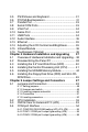
Contents Chapter 1 General Information 1 1.1 Introduction ............................................................. 2 1.2 How to Use This Manual .......................................... 4 1.3 Specifications ......................................................... 6 General .................................................................................... 6 Standard PC functions ............................................................. 6 Flat panel interface .....................................
3.5 PS/2 Mouse and Keyboard ................................... 31 3.6 PCI/ISA Bus Expansion ......................................... 31 3.7 Parallel Port .......................................................... 33 3.8 Serial COM Ports.................................................. 33 3.9 VGA Port .............................................................. 34 3.10 Game Port ............................................................ 34 3.11 USB Ports ...............................................
5.5 5.6 Internal -12 V source selection setting (JP1) .......... 56 VGA Interface ....................................................... 57 5.6.1 LCD panel power setting ............................................... 57 5.6.2 Panel type select (SW3) ............................................... 57 5.7 Watchdog Timer Configuration .............................. 58 5.7.1 Watchdog activity selection (JP7) ................................. 58 Chapter 6 PCI Bus Ethernet Interface 59 6.1 Introduction ....
9.3 Standard CMOS Setup ......................................... 85 9.3.1 Hard Disk Configurations ............................................... 86 9.4 BIOS Features Setup ............................................ 87 9.5 Chipset Features Setup ........................................ 91 9.6 Power Management Setup .................................... 93 9.7 PNP/PCI Configuration Setup ............................... 96 9.8 Load BIOS Defaults .............................................. 97 9.
Appendix B Programming the Watchdog Timer 127 B.1 Programming the Watchdog Timer ...................... 128 Appendix C Full Disassembly Procedures 131 C.1 Full Disassembly Procedures .............................. 132 Appendix D Pin Assignments 139 D.1 AT Power Connector (J1) .................................... 140 D.2 TV Output Connector (J2) (*Reserved) ................ 140 D.3 Inverter Power Connector (J4) ............................. 141 D.4 Internal Speaker Connector (J6) ..........................
Figures Figure 1-1: The panel PC in perspective ............................................... 3 Figure 1-2: How to read the PPC-123 manual ....................................... 5 Figure 1-3: Dimensions of the PPC-123 .............................................. 10 Figure 2-1: Front view of the panel PC ................................................ 12 Figure 2-2: Left side view of the panel PC ........................................... 13 Figure 2-3: Rear view of the panel PC ......................
Figure C-1: Disassembly steps 1 - 4 ................................................ 133 Figure C-2: Disassembly steps 5 - 6 ................................................ 135 Figure C-3: Disassembly steps 7 - 11 ............................................... 137 Figure E-1: Cutout dimensions of the PPC-123 ................................ 158 Figure E-2: Panel mounting .............................................................. 159 Figure E-3: Desktop stand mounting ..................................
Tables Table 5-1: Jumpers and their functions ............................................... 49 Table 5-2: Panel PC connectors ......................................................... 51 Table 5-3: Clear CMOS / External RTC (JP8) ...................................... 53 Table 5-4: COM2 RS-232/422/485 setting (JP3, JP4) .......................... 54 Table 5-5: COM2 RS-232/422/485 setting (JP5) .................................. 54 Table 5-6: Serial port default settings ...................................
CHAPTER 1 General Information This chapter gives background information on the PPC-123 panel PC.
1.1 Introduction The PPC-123 panel PC is a multimedia Pentium® III processor-based computer that is designed to serve as a human machine interface (HMI) and as a desktop computer. It is a PC-based system with 12.1" color TFT LCD display, on-board PCI Ethernet controller, multi-COM port interfaces and a 16-bit stereo audio controller. With built-in CD-ROM drive, floppy drive and PCMCIA expansion sockets, the PPC-123 is as compact and user-friendly as a notebook computer.
CRT Monitor Touchscreen Network Fax modem Speakers Printer Keyboard Joystick Mouse Figure 1-1: The panel PC in perspective Chapter 1 General Information 3
1.2 How to Use This Manual This manual contains all the information you need to set up and use the panel PC. In addition to this manual, you may also want to consult the manuals for your operating system, software applications and peripherals. Whether you are a new or an experienced user, you will benefit more from this manual if you are familiar with its organization. This manual is divided into ten chapters, plus five appendices.
PC. Appendix D includes all pin assignments on the connectors. Appendix E helps users install the panel PC, which is mountable in a variety of ways. If you are a commercial user and the panel PC unit you bought is a complete set with CPU, hard disk drive, SDRAM, CD-ROM drive, floppy disk drive and PCMCIA expansion slots included, you may only need to read Chapters 1 through 3 regarding hardware operation. For additional drivers and BIOS setup information, you should read Chapters 6 through 10.
1.3 Specifications General • Dimensions (W x H x D): 375 x 285 x 93.3 mm (14.7" x 11.2" x 3.7") • Weight: 5.2 kg (11.5 lb) • Power supply: AC model: 80 watts Input voltage: 100~250 VAC , 3 A max. @ 50 ~ 60 Hz Output voltage: +5 V @ 12 A, +12 V @ 1 A DC model: 60 watts Input voltage: 24 VDC , 5 A max or 12 VDC, 7 A max Output voltage: +5 V @ 10 A, +12 V @ 1 A • Cooling fan dimensions (L x W x H): Power fan: 40 x 40 x 10 mm (1.6" x 1.6" x 0.4") CPU fan: 60 x 60 x 10 mm (2.4" x 2.4" x 0.
•Floppy disk drive: Supports up to two FDDs (720 KB / 1.44 MB). One built-in FDD included inside FDD housing. • Parallel port: One parallel port, supports SPP/EPP/ECP parallel mode. BIOS configurable to LPT1, LPT2, LPT3 or disabled • Serial ports: Four serial ports with three RS-232 ports (COM1, 3, and 4), one RS-232/422/485 port (COM2).
• Audio interface: Microphone-in, Line-in, Line-out and Game ports (MPU-401) PCI bus Ethernet interface • Chipset: Realtek RTL 8139 PCI local bus Ethernet controller • Ethernet interface: Full compliance with IEEE 802.3u 100Base-T and 10Base-T specifications.
Note: The panel PC with the optionally installed touchscreen will share COM4. Once the touchscreen is installed, COM4 cannot be used for other purposes. Optional modules • CPU: Intel® Celeron™ or Pentium® III up to 850 MHz • Memory: 32/64/128/256 MB SDRAM • HDD: 2.5" HDD • Touchscreen: Analog resistive or capacitive • CD-ROM drive: Compact 24X CD-ROM or above • DVD-ROM drive: Compact 6X DVD-ROM or above • PCMCIA interface: Complies with 1995 PCMCIA card standard. Supports two PCMCIA card/CardBus slots.
1.
CHAPTER System Setup • A Quick Tour of the Panel PC • Preparing for First-time Usage • Running the Setup Program • Installing the System Software • Installing the Drivers 2
2.1 A Quick Tour of the Panel PC Before you start to set up the panel PC, take a moment to become familiar with the locations and purposes of the controls, drives, connectors and ports, which are illustrated in the figures below. When you place the panel PC upright on the desktop, its front panel appears as shown in Figure 2-1.
When you look at the left side of the panel PC, you will see the floppy disk drive, CD-ROM drive and PCMCIA expansion sockets, as shown in Fig. 2-2. FDD eject button FDD slot FDD activity light Compact CD-ROM drive CD-ROM drive activity light CD-ROM eject button PCMCIA socket PCMCIA eject button Figure 2-2: Left side view of the panel PC When you turn the panel PC around and look at its rear cover, you will find the PCI/ISA expansion slot located on the left side.
PCI/ISA expansion slot cover PS/2 mouse and keyboard connector USB ports Ethernet jack Brightness adjust knob Contrast adjust knob Line-out jack Line-in jack Microphone-in jack Parallel port Serial ports VGA port Game port Figure 2-3: Rear view of the panel PC Figure 2-4 shows the I/O section and power switch of the panel PC.
2.2 Preparing For First-time Use Before you start to set up the panel PC system, you should have at least the following items ready: • Power cord (in the accessory box) • Y-shaped connector (in the accessory box) • keyboard • Mouse (for system software installation i.e. Microsoft Windows, NT, etc.) 2.3 Installation Procedures 2.3.1 Connecting the power cord The panel PC can only be powered by an AC electrical outlet (100 ~ 250 volts, 50 ~ 60 Hz).
2.3.2 Installing the DC power insulator with hood The panel PC can also be powered by DC electrical outlet (24 VDC or 12 VDC, which depends on the power type). Follow the procedure in order to install the DC power insulator with hood then make sure to connect the insulator with the system. STEP 1. Connect the three contact pins individually to the negative and positive power cables of the power adaptor, as well as to the frame ground cable. Solder firmly.
frame ground ( G ), and pin 3 should be plugged into the negative DC power input ( - ). STEP 3: Mount the front part of the male insulator onto the bottom tray. STEP 4: Use the metal plate and the two screws to secure the cables to the bottom tray. Please refer to the illustration above.
STEP 5: Attach the upper cap to the bottom tray and secure it with the screws. STEP 6: Now that you have completed the assembly of the male insulator, plug it into the female insulator.
2.3.3 Connecting the keyboard and mouse 1. Connect the Y-shaped adapter to the PS/2 mouse and keyboard port on the I/O section of the panel PC. (See Fig. 2-6.) 2. Connect the PS/2 mouse and keyboard to the Y-shaped adapter. (See Fig. 2-6.) If you use a serial mouse and your panel PC has a touchscreen, you can connect the mouse to any COM port except COM4. Y-shaped adapter PS/2 mouse and keyboard port PS/2 mouse Keyboard Figure 2-6: Connecting the keyboard and mouse 2.3.
2.4 Running the BIOS Setup Program Your panel PC is likely to have been properly set up and configured by your dealer prior to delivery. You may still find it necessary to use the panel PC's BIOS (Basic Input-Output System) setup program to change system configuration information, such as the current date and time or your type of hard drive. The setup program is stored in readonly memory (ROM).
2.5 Installing System Software Recent releases of operating systems from major vendors include setup programs which load automatically and guide you through hard disk preparation and operating system installation. The guidelines below will help you determine the steps necessary to install your operating system on the panel PC hard drive. Note: Some distributors and system integrators may have already pre-installed system software prior to shipment of your panel PC.
2.6 Installing the Drivers After installing your system software, you will be able to set up the Ethernet, SVGA, audio, PCMCIA and touchscreen functions. All the drivers except the CD-ROM drive driver are stored in a CD-ROM disc entitled "Drivers and Utilities." The CD-ROM drive driver is stored in a floppy disk. Both the CD-ROM and the floppy disk can be found in your accessory box.
The various drivers and utilities in the CD-ROM disc have their own text files which help users install the drivers and understand their functions. These files are a very useful supplement to the information in this manual. Note: The drivers and utilities used for the PPC-123 panel PCs are subject to change without notice. If in doubt, check Advantech's website or contact our application engineers for the latest information regarding drivers and utlities.
24 PPC-123 User's Manual
CHAPTER 3 Using the Panel PC • Floppy Drive • CD-ROM Drive • PCMCIA Sockets • PS/2 Mouse and Keyboard • Audio Interface • PCI/ISA Bus Expansion • Parallel Port • Serial COM Ports • VGA Port • Game Port • USB Ports • Audio Interface • Ethernet • Adjusting the LCD Contrast and Brightness • Infrared module • Touchscreen (Optional)
3.1 Introduction This chapter describes basic features and procedures for using the panel PC. Topics covered include the floppy drive, CD-ROM drive, I/O ports, touchscreen, and so on. 3.2 Floppy Drive To insert a diskette, hold it with your left hand, between your thumb and your other fingers, and push it toward the drive. (See Fig. 3-1.) Slide the disk until it clicks into place. Note that new diskettes must be formatted by your operating system before you can use them for data storage.
3.3 CD-ROM Drive To insert a CD-ROM disc, press the eject button of the CD-ROM drive. The yellow activity light will flash and the front panel will come out a short distance. Using your fingertips, hold the top and bottom of the front panel and pull it outward to the very end. (See Fig 3-2.) Align the center hole of the CD-ROM disc with the center circle of the CD-ROM holding plate. Press the transparent ring around the center hole of the CD-ROM until you hear a click.
3.4 PCMCIA PCMCIA cards are inserted and ejected in much the same way as diskettes. To insert a PCMCIA card, align the card with the socket and slide the card into the socket until it locks into place. Note that some PCMCIA memory cards must be prepared by your operating system before you can use them for data storage. See your PCMCIA card manual for details. To eject a PCMCIA card, first ensure that the panel PC is not accessing the memory card or device.
Network USB keyboard PS/2 mouse Printer Figure 3-4: Using the I/O interface (upper level ports excluding COM ports) Chapter 3 Using the Panel PC 29
Headphones CD-ROM player Microphone Joystick CRT monitor Serial mouse Figure 3-5: Using the I/O interface (lower level ports and COM ports) 30 PPC-123 User's Manual
3.5 PS/2 Mouse and Keyboard If you wish to use a full-size desktop keyboard and PS/2 mouse with your panel PC, follow these instructions: 1. Be sure the panel PC is turned off. 2. Connect the Y-shaped adapter to the PS/2 mouse and keyboard port on the rear bottom side of the rear cover. (See Fig. 3-4 and Fig. 2-6.) 3. Attach the keyboard to the 5-pin port of the Y-shaped adapter. 4. Attach the PS/2 mouse to the 6-pin female PS/2 port of the Y-shaped adapter. 5. Turn on the panel PC. 3.
PCI/ISA expansion slot cover PCI/ISA bus card Metal plate Figure 3-6: PCI/ISA bus expansion 32 PPC-123 User's Manual
3.7 Parallel Port The panel PC supports the latest EPP and ECP parallel port protocols for improved performance and versatility with compatible printers or other devices. To connect the panel PC to a printer or other devices: 1. Be sure both the panel PC and the printer/devices are turned off. 2. Connect the 25-pin male connector of the printer cable to the 25-pin female port on the panel PC labelled "parallel port". 3.
3.9 VGA Port An external VGA-compatible device may be connected to the system through the 15-pin external port located on the rear of the system unit. The panel PC simultaneously supports an external CRT monitor in addition to its own LCD display. 1. Be sure the panel PC is turned off. 2. Connect the external monitor to the system. (See Fig. 3-5.) 3. Turn on the panel PC and the external monitor. 3.
3.12 Audio Interface The audio interface includes three jacks: microphone in, line out and line in. (See Fig. 3-5.) Their functions are: Microphone in: Use an external microphone to record voice and sound. Line out: Output audio to external devices such as speakers or earphones. Line in: Input audio from an external CD player or radio. 1. Connect the audio device to the system. (See Fig. 3-5.) 2. Install the driver before you use the device. 3.
3.15 Infrared Module This sensor on the front panel supports the optional wireless transmitting and receiving of infra-red data. (See Fig. 2-1.) You must configure the setting through the BIOS setup (chipset features) to select whether UART2 is directed for use with COM2 or IrDA. 1. Place the panel PC and the infrared transceiving device (eg. printer) with their IrDA ports facing each other at the same horizontal level. The distance between the two IrDA ports should not exceed 1 meter (38"). 2.
CHAPTER 4 Hardware Installation and Upgrading • Overview of Hardware Installation and Upgrading • Disassembling the Panel PC • Installing the 2.
4.1 Overview of Hardware Installation and Upgrading The panel PC consists of a PC-based computer that is housed in a plastic rear panel and a metal shielding case. Your HDD, SDRAM, power supply, CPU, and so on are all readily accessible by removing the rear panel and shielding case. Any maintenance or hardware upgrades can be easily completed after removing the rear panel and shielding case.
Plastic rear cover CPU fan and cover PCI/ISA expansion PCB Side panel Figure 4-1: Disassembling the plastic rear cover of the panel PC Chapter 4 Hardware Installation and Upgrading 39
4.3 Installing the 2.5" Hard Disk Drive (HDD) You can attach one enhanced Integrated Device Electronics (IDE) hard disk drive to the panel PC's internal controller which uses a PCI local-bus interface. The advanced IDE controller supports faster data transfer and allows the IDE hard drive to exceed 528 MB. The following are instructions for installation: 1. Detach and remove the plastic rear cover and side panel. 2.
4.4 Installing the Central Processing Unit (CPU) The panel PC's central processing unit (CPU) can be upgraded to improve system performance. The panel PC provides one 370-pin ZIF (Zero Insertion Force) socket (Socket 370). The CPU must come with an attached heat sink and CPU fan to prevent overheating. Warning! The CPU may be damaged if operated without a heat sink and a fan. Caution! Always disconnect the power cord from your panel PC when you are working on it.
8. Insert the CPU with the correct orientation. The notched corner of the CPU (with the white dot) should point towards the end of the lever. The end of the lever is the blank area where one hole is missing from the corner of the square array of pin holes. An arrowhead printed on the motherboard points to the end of the lever. (See Fig. 4-3 overleaf.) 9. Slide the CPU in gently. It should insert easily.
CPU fan CPU cover Heat sink clip Heat sink CPU Lever Socket 370 Figure 4-3: Installing the CPU Chapter 4 Hardware Installation and Upgrading 43
4.5 Installing the SDRAM Memory Module You can install from 32 to 256 MB of SDRAM memory. The panel PC system provides one 168-pin DIMM (Dual Inline Memory Module) socket and supports 3.3 V SDRAM with a minimum speed of 12 ns. Note: The module can fit into the socket only one way. Pin 1 of the DIMM module must line up with the small arrowhead printed on the motherboard next to the DIMM socket. The golden pins of the module must point down into the DIMM socket. 1.
4.6 Installing the Floppy Disk Drive (FDD) and Slim CD-ROM Drive Installation of a floppy disk drive and slim CD-ROM drive is similar to that for a hard disk drive. The metal plate for holding the FDD and the CD-ROM support bracket are on the left side of the shielding case. The 26-pin and 40-pin yellow FPC cables are for connecting the FDD and CD-ROM respectively. Only 3.5" floppy disk drives (720 KB and 1.44 MB) and slim CD-ROM drives can be attached to the metal plate and CD-ROM support bracket. 1.
9. Connect the FDD cable (26-pin to 26-pin) and CD-ROM cable (40-pin to 40-pin). The other end of the FDD cable is connected to connector CN10 on the PC board. The other end of the CD-ROM cable is connected to connector CN18 on the PC board. 10. Slide the FDD assembly and slim CD-ROM assembly toward the inside of the panel PC, as far as they will go. 11. Secure the two screws ("A") of the metal plate to the shielding case. 3.
CHAPTER 5 Jumper Settings and Connectors This chapter tells how to set up the panel PC hardware, including instructions on setting jumpers and connecting peripherals, switches and indicators. Be sure to read all the safety precautions before you begin the installation procedures.
5.1 Jumpers and Connectors 5.1.1 Setting jumpers You can configure your panel PC to match the needs of your application by setting jumpers. A jumper is the simplest kind of electrical switch. It consists of two metal pins and a small metal clip (often protected by a plastic cover) that slides over the pins to connect them. To “close” a jumper, you connect the pins with the clip. To “open” a jumper you remove the clip. Sometimes a jumper will have three pins, labeled 1, 2, and 3.
5.1.2 Jumpers and switch The motherboard of the panel PC has a number of jumpers that allow you to configure your system to suit your applications. The table below lists the function of each of the board’s jumpers.
5.1.
5.1.4 Connectors Onboard connectors link the panel PC to external devices such as hard disk drives or floppy drives. The table below lists the function of each of the board’s connectors.
5.1.
5.2 CPU Installation You can install an Intel Celeron™ or Pentium® III CPU without setting any frequency ratio or voltage. 5.3 CMOS Clear for External RTC (JP8) Warning: To avoid damaging the computer, always turn off the power supply before setting “Clear CMOS”. Set the jumper back to “Normal operation” before turning on the power supply.
5.4 COM-port Interface The panel PC provides four serial ports (COM1, 3, 4: RS-232; COM2: RS-232/422/485) in one COM port connector. 5.4.1 COM2 RS-232/422/485 setting (JP3, JP4, JP5) COM2 can be configured to operate in RS-232, RS-422, or RS-485 mode. This is done via JP3, JP4 and JP5.
COM1 and COM2 are one set. You can exchange the address range and interrupt IRQ of COM1 for the address range and interrupt IRQ of COM2. After exchanging, COM1's address range is 2F8 ~ 2FF and its request IRQ is IRQ3: and COM2's address range is 3F8 ~ 3FF and its interrupt IRQ is IRQ4. COM3 and COM4 are another set. Their selectable function is the same as the COM1/COM2 set.
5.4.3 COM3 / COM4 pin 9 output type setting (JP6) Table 5-8: COM3/COM4 pin 9 output type setting (JP6) *Normal operation +5 V output +12 V output 6 5 6 5 6 5 4 3 4 3 4 3 2 1 2 1 2 1 * default setting Note: 5.5 Pins 1, 3 and 5 are for COM3. Pins 2, 4 and 6 are for COM4. Internal -12 V source selection setting (JP1) The panel PC provides an internal -12 V source in an extension slot available for various extension card applications.
5.6 VGA Interface The panel PC's AGP VGA interface can drive conventional CRT displays. It is also capable of driving a wide range of flat panel displays, including electroluminescent (EL), gas plasma, passive LCD and active LCD displays. The board has two connectors to support these displays simultaneously: one for standard CRT VGA monitors, and one for flat panel displays. CRT display port information can be found in Section 3.9 this manual.
5.7 Watchdog Timer Configuration An onboard watchdog timer reduces the chance of disruptions which EMP (electromagnetic pulse) interference can cause. This is an invaluable protective device for standalone or unmanned applications. Setup involves one jumper and running the control software. (Refer to Appendix B.) 5.7.1 Watchdog activity selection (JP7) When the watchdog timer activates (i.e. CPU processing has come to a halt), it can reset the system or generate an interrupt on IRQ11.
CHAPTER 6 PCI Bus Ethernet Interface This chapter provides information on Ethernet configuration.
6.1 Introduction The PPC-123 is equipped with a high performance 32-bit Ethernet chipset which is fully compliant with IEEE 802.3 100 Mbps CSMA/ CD standards. It is supported by major network operating systems. It is also both 100Base-T and 10Base-T compatible. The medium type can be configured via the RSET8139.exe program included on the utility disk. The Ethernet port provides a standard RJ-45 jack.
6.2.1 Installation for Windows 95 1. a. Select "Start", "Settings", "Control Panel", "System". b. Click the "Device Manager" and "Other Devices" items. c. Remove the "PCI Ethernet Controller" item. 2. a. Select "Start", "Settings", "Control Panel", and "Network" icons. b. Click the "Add" button. 3. a. Select "Adapter", and then click the "Add" button. 4. a. Press the "Have Disk..." button.
5. a. Type the path "D:\ PPC123~7\LAN\ W95OSR2" b. Click the "OK" button. 6. 7. 8. a. Choose the highlighted "Realtek RTL8139(A/B/C/ 8130)PCI Fast Ethernet". b. Press the "OK" button. a. Press the "Add..." button to select suitable services or protocol. b. Press the "OK" button to finish network configuration. a. Press the "Yes" button to start your computer.
6.2.2 Installation for Windows 98 a. Select "Start", "Settings", "Control Panel", "System" 1. b. Click "Device Manager" and highlight "PCI Ethernet Controller" c. Select "Properties" 2. a. Choose "Driver" folder 3. a. Click "Update Driver" 4. a. Follow the instructions b.
5. a. Click "Next" 6. a. Select "Network Adaptors" b. Click "Next" 64 7. a. Choose "Have Disk" 8. a. Type the path "D:\ 123&153\LAN\WIN98" b.
9. a. Click "OK" 10. a. Click "Next" 11. a. Click "Finish" 12. a.
6.2.3 Installation for Windows NT 1. a. Select "Start", "Settings", "Control Panel", and then double click the "Network" icon. b. Choose the "Adapters" label. c. Click the "Add" button. 2. a. Press "Have Disk...". 3. a. Type the path "D:\ PPC123&153\LAN\ WINNT. b. Press the "OK" button.
4. a. Choose the highlighted "RTL8139(A/B/C/ 8130)PCI Fast Ethernet Adapter. b. Click the "OK" button. 5. a. Choose a suitable RTL8139 Duplex mode for your application. 6. a. Finish the network configuration and then click the "OK" button. end 6.2.
6.3 Further Information Realtek website: www.realtek.com.tw Advantech websites: www.advantech.com www.advantech.com.
CHAPTER AGP SVGA Setup • Introduction • Installation of SVGA Driver - for Windows 95/98 - for Windows NT - for Windows 2000 - for Windows ME • Further Information 7
7.1 Introduction The PPC-123 has an onboard AGP flat panel/VGA interface. The specifications and features are described as follows: 7.1.1 Chipset The PPC-123 uses a Lynx3DM8 SMI721 chipset from Silicon Motion Inc. for its AGP/SVGA controller. It supports many popular LCD, EL, and gas plasma flat panel displays and conventional analog CRT monitors. The SMI721 VGA BIOS supports monochrome LCD, EL, color TFT and STN LCD flat panel displays.
7.2 Installation of SVGA Driver Complete the following steps to install the SVGA driver. Follow the procedures in the flow chart that apply to the operating system that you you are using within your PPC-123. Important: The following windows illustrations are examples only. You must follow the flow chart instructions and pay attention to the instructions which then appear on your screen. Note 1: The CD-ROM drive is designated as "D" throughout this chapter.
7.2.1 Installation for Windows 95/98 1. a. Select "Start", "Run" b. Type the path "D:\ 123&153\VGA(3DM)\ Win9x\Setup.exe c. Click "OK" a. Click "Next" 2. 3. a.
7.2.2 Installation for Windows NT 1. a. Select "Start", "Run" b. Type the path "D:\ 123&153\ VGA(3DM)\WinNT\ Setup.exe c. Click "OK" a. Click "Next" 2. 3. a. Click "Finish" to reboot the system End Note: Service Pack X (X=3, 4, 5, 6...) must be installed first before you install the Windows NT VGA driver.
7.2.3 Installation for Windows 2000 1. a. Select "Start", "Run" b. Type the path "D:\ 123&153\VGA(3DM)\ Win2000\Setup.exe c. Click "OK" a. Click "Next" 2. 3. a.
7.2.4 Installation for Windows ME 1. a. Select "Start", "Run" b. Type the path "D:\ 123&153\VGA(3DM)\ WinME\Setup.exe c. Click "OK" a. Click "Next" 2. 3. a.
7.3 Further Information For further information about the AGP SVGA installation in your PPC-123, including driver updates, troubleshooting guides and FAQ lists, visit the following web resources: Silicon Motion website: www.siliconmotion.com Advantech websites: www.advantech.com www.advantech.com.
CHAPTER Audio • Introduction • Installation of Audio Driver - for Windows 95/98 - for Windows NT - for Windows 2000/ME 8
8.1 Introduction The PPC-123's onboard audio interface provides high-quality stereo sound and FM music synthesis (ESFM) by using the ES1946S audio controller from ESS Technology, Inc. The audio interface can record, compress, and play back voice, sound, and music with a built-in mixer control. The PPC-123's onboard audio interface also supports the Plug and Play (PnP) standard and provides PnP configuration for audio, FM, and MPU-104 logical devices.
8.2.1 Installation for Windows 95/98 1. a. Select "Start", "RUN". b. Enter the driver path: "D:\ PPC123&153\ Audio\win9x(only)\ Setup.exe" 2. a. Click "Next" to continue the installation. 3. a. Select "Upgrade Drivers". b. Click "Next". 4. a. When installation is completed, click "Finish" to restart your computer.
5. a. After installation, select "Start", "Settings", "Control Panel", "System". b. Click the "Device Manager" tab to see the result of your installation.
8.2.2 Installation for Windows NT 1. 2. a. Select "Start", "Settings", "Control Panel". b. Double Click the "Multimedia" icon. a. Select the "Devices", item. b. Click the "Add..." button. 3. a. Choose the "Unlisted or Updated Driven" item. b. Click the "OK" buttom. 4. a. Type the path "D:\ ppc123&153\audio\ nt40\ b. Click the "OK" buttom.
5. 6. a. Slecte the highlighted item. b. Press the "OK" buttom. a. Press the "Restart Now" buttom to reboot your computer. End 8.2.3 Installation for Windows 20000/ME After finishing the Windows 2000 or Windows ME installation, the system can automatically detect the audio hardwre and install the driver from the driver database in Windows 2000 or Windows ME when the system reboots. It is not necessary to install the audio driver manually.
CHAPTER 9 Award BIOS Setup This chapter describes how to set BIOS configuration data.
9.1 Award BIOS Setup The PPC-123 comes with an Award BIOS chip that contains the ROM setup for your system. This chip serves as an interface between the processor and the rest of the mainboard's components. This chapter explains the information contained in the setup program and tells you how to modify the settings according to your system configuration. Some setup items will not be explained, because it is recommended that users do not change such items.
A setup program, built into the system BIOS, is stored in the CMOS RAM that allows the configuration settings to be changed. This program is executed when the user changes the system configuration; when the user changes the system backup battery; or when the system detects a configuration error and asks the user to run the setup program. At power-on RAM testing, the message "Press DEL to enter Setup" appears. After pressing the "DEL" key, the CMOS setup utility screen will appear as shown in Fig. 9-1.
9.3.1 Hard Disk Configurations TYPE Select from 1 to 45 to fill the remaining fields with predefined values for disk drives. Select "User" to fill the remaining fields. Select "Auto" to detect the HDD type automatically. SIZE Hard disk size. The unit is megabytes (MB). CYLS The cylinder number of the hard disk. HEAD The read/write head number of the hard disk. PRECOMP The cylinder number at which the disk drive changes the write timing.
9.4 BIOS Features Setup Figure 9-3: BIOS features setup screen Moving around the BIOS Features and Chipset Features setup programs works the same way as moving around the Standard CMOS setup program. (Refer to the next section for Chipset Features setup.) The BIOS Features setup program is shown above. Users are not encouraged to run the BIOS and Chipset Features setup programs. Your system should have been fine-tuned before shipping.
External Cache When enabled, supports an external cache SRAM. The options are: Enabled (Default), Disabled. CPU L2 Cache ECC Checking Allows the CPU L2 cache to enable the memory parity check. The options are: Disabled (Default), Enabled. Quick Power On Self Test When enabled, allows the BIOS to bypass the extensive memory test. The options are: Disabled (Default), Enabled. Boot From LAN First Enables the system to boot from a LAN. The options are: Disabled (Default), Enabled.
Swap Floppy Drive When enabled, allows you to switch the order in which the operating system accesses the floppy drives during boot-up. The options are: Disabled (Default), Enabled. Boot Up Floppy Seek When enabled, assigns the BIOS to perform floppy disk drive tests by issuing seek commands. Note that such tests are time-consuming. The options are: Enabled (Default), Disabled. Boot Up NumLock Status When set to "On", allows the BIOS to automatically enable the NumLock function when the system boots up.
The options are: Disabled (Default), Enabled. PCI/VGA Palette Snoop When enabled, allows you to install an enhanced graphics adapter card. If your graphics adapter card does not support the Palette Snoop function, set at "Disabled" to avoid system malfunctions. The options are: Disabled (Default), Enabled. OS Select For DRAM > 64MB If your operating system (OS) is OS2, select "OS2". Otherwise, stay with the default setting Non-OS2. Report No FDD For WIN 95 Assigns IRQ6 for the FDD.
9.5 Chipset Features Setup Note: It is strongly recommended that setup items in this section NOT be changed, because advanced knowledge is required to effect such changes. Figure 9-4: Chipset features setup screen EDO CASX# MA Wait State Sets the EDO CASX# MA wait state. The options are: 1 (Default), 2. EDO RASX# Wait State Sets the EDO RASX# wait state. The options are: 1 (Default), 2. SDRAM CAS Latency Time Sets the SDRAM CAS latency time. The options are: Auto (Default), 2, 3.
SDRAM Data Integrity Mode When set as Non-ECC, supports standard 64-bit DIMM RAM modules. When set as ECC, supports standard 72-bit ECC RAM modules. The options are: Non-ECC (Default), ECC. System BIOS Cacheable When enabled, allows the ROM area FOOOH-FFFFH to be cacheable when the cache controller is activated. The recommended setting is "Disabled", especially for high speed CPUs (200 MHz and above).
Delayed Transaction When disabled, the syatem operates normally. When enabled, the system can support lower-speed ISA devices. The options are: Disabled (Default), Enabled. Spread Spectrum When disabled, the syatem operates normally. When enabled, the spread spectrum will be set to 0.5% (CNTR). The options are: Disabled (Default), Enabled. 9.6 Power Management Setup Figure 9-5: Power Management setup screen Power Management When enabled, allows you to use Power Management features.
PM Control by APM The option "No" allows the BIOS to ignore the APM (Advanced Power Management) specification. Selecting "Yes" will allow the BIOS to wait for APM's prompt before it enters Doze mode, Standby mode, or Suspend mode. If the APM is installed, it will prompt the BIOS to set the system into power saving mode after all tasks are done. The options are: Yes (Default), No. Video Off Option This feature provides the selections for the video display power saving mode.
Standby Mode The system will not enter Standby mode, because this option is designated as "Disabled". Suspend Mode The system will not enter Suspend mode, because this option is designated as "Disabled". HDD POWER Down Selecting "Disabled" will turn off the hard disk drive (HDD) motor. Selecting "1 Min.. 15 Min" allows you to define the HDD idle time before the HDD enters Power Saving Mode. The options "1 Min.. 15 Min" and "When Suspend" will not work concurrently.
9.7 PNP/PCI Configuration Setup Figure 9-6: PNP/PCI configuration setup screen PNP OS Installed Select Yes if the installed system supports the PnP function. Select No if the installed system does not support the PnP function. The options are: No (Default), Yes. Resources Controlled By If set at "Auto", the BIOS automatically arranges all system resources for you.
The options are: Disabled (Default), Enabled. Used MEM base addr Choose and use the MEM base address. The options are: N/A (Default), C800 ~ DC00. Assign IRQ for USB Assigns an IRQ for the USB. The options are: Disabled (Default), Enabled. 9.8 Load BIOS Defaults Figure 9-7: Load BIOS defaults screen The BIOS defaults screen contains the most appropriate values of the system parameters that allow minimum system performance. 9.
9.10 Integrated Peripherals Figure 9-8: Integrated peripherals screen IDE HDD Block Mode This allows your hard disk controller to use the fast block mode to transfer data to and from your hard disk drive (HDD). The options are: Enabled (Default), Disabled. IDE Primary/Secondary Master/Slave PIO IDE hard disk drive controllers can support up to separate hard drives. These drives have a master/slave relationship which is determined by the cabling configuration used to attach them to the controller.
Your system supports five modes, numbered from 0 through 4, which differ primarily in timing. When "Auto" is selected, the BIOS will choose the best available mode. The options are: Auto, (Default), Disabled. Primary/Secondary Master/Slave Ultra DMA DMA means Direct Memory Access. Ultra DMA is faster than DMA. DMA is a method of transferring data to or from memory at a fast rate, without involving the CPU. When you select "Auto", the BIOS will choose the best available mode.
The options are: 378/IRQ7 (Default), 3BC/IRQ7, 278/IRQ5, Disabled. Parallel Port Mode You can choose different data transfer modes for your system. The options are: ECP & EPP (Default), SPP, EPP, ECP. ECP Mode Use DMA You can choose different DMA modes for data transfer. The options are: 3 (Default), 1. 9.11Password Setting To enable the password setting, select the item from the Standard CMOS Setup. You will be prompted to create your own password.
9.12 IDE HDD Auto Detection Figure 9-9: IDE HDD auto detection screen The IDE Hard Disk Drive Auto Detection feature automatically configures your new hard disk. Use it for quick configuration of new hard disk drives. This feature allows you to set the parameters of up to four IDE HDDs. The option with "(Y)" is recommended by the system BIOS. You may also key in your own parameters instead of setting them according to the system BIOS. After keying in all settings, press "Esc" to return to the main menu.
9.13 Save and Exit Setup Figure 9-10: Save and exit setup screen After you have made changes in the BIOS setup, press "Esc" to return to the main menu. Move the cursor to "Save and Exit Setup", or press "F10" and then press "Y", to change the CMOS Setup. If you did not change anything, press "Esc" again or move the cursor to "Exit Without Saving" and press "Y" to retain the setup settings.
CHAPTER 10 PCMCIA • Introduction • Installation of PCMCIA Driver - for Windows 95
10.1 Introduction The PPC-123 is equipped with a high performance PCMCIA interface which complies with the 1995 PCMCIA card standard by using the RICOH Cardbus controller. The panel PC supports two PCMCIA card/cardbus slots. Two sockets support both a 16-bit PCMCIA card and a 32-bit Cardbus simultaneously, with hot insertion and removal. 10.2 Installation of PCMCIA Driver The PCMCIA driver for Windows 95 is included in the "Drivers and Utilities" CD-ROM included with your PPC-153.
10.2.1 Installation for Windows 95 1. a. In "Start", "Run", type the path: D:\ PPC123&153\ Cardbus\win95osr2\ Setup.exe 2. a. Click "Next". 3. a. Click "Yes". 4. a. Click "Finish" to reboot the system.
106 PPC-123 User's Manual
CHAPTER 11 Touchscreen • Introduction • Installation of Driver for Resistive Touchscreen - for Windows 95 - for Windows 98 - for Windows NT - for Windows 2000 - for Windows ME • Installation of Driver for Capacitive Touchscreen - for Windows 95/98/NT
11.1 Introduction 11.1.1 General information The PPC-123's optional touchscreen incorporates advanced second-generation 5-wire resistive or impact-resistant capacitive technology. They allow 75% and 85% light transmission respectively and have an antiglare surface. All models provide greatly enhanced visual resolution. They also have new improved scratch-resistant features. The touchscreen is manufactured from UL-recognized components.
the following chemicals when exposed for a period of one hour at a temperature of 21° C (71° F): - Acetone - Methylene chloride - Methyl ethyl ketone - Isopropyl alcohol - Hexane - Ammonia-based glass cleaners - Turpentine - Mineral spirits - Foods and beverages 11.2 Installation of Driver for Resistive Touchscreen The touchscreen driver for Windows 95/98 contains a native, 32-bit driver and a 32-bit control panel program for the PPC-123 system.
11.2.1 Installation for Windows 95 110 1. a. Insert the "Drivers and Utilities" CD. b. Click the "Start" button, and then "Run". c. Type the path "D:\ PPC123&153\ Elotouch\Win95\ Setup.exe". 2. a. Click "Yes". 3. a. Select the "Smart serial Controller on COM4" item. b. Press the "OK" buttom. 4. a. Click the "Yes" buttom to restart your computer.
5. a. Touch targets to calibrate the touchscreen controller.
11.2.2 Installation for Windows 98 If you want to use the touchscreen driver CD-ROM accompanying your panel PC, refer to the following flow chart instructions. 112 1. a. Insert the "Drivers and Utilities" CD. b. Click the "Start" button, and then "Run". c. Type the path "D:\ PPC123&153\ Elotouch\Win98\ Setup.exe". 2. a. Click "Yes". 3. a. Select the "Smart serial Controller on COM4" item. b. Press the "OK" buttom. 4. a. Click the "Yes" buttom to restart your computer.
5. a. Touch targets to calibrate the touchscreen controller.
11.2.3 114 Installation for Windows NT 1. a. Select "Start", "Run". b. Type the path "D:\ PPC123&153\ Elotouch\WINNT\ Setup.exe" 2. a. Press the "Next" button. 3. a. Set the directory path. 4. a. Choose a suitable item.
5. a. Chose COM4. b. Press "OK". 6. a. Click "OK" to reboot the System. 7. a. Calibrate the touchscreen.
11.2.4 Intallation for Windows 2000 1. a. Select "Start", "Run" b. Type the path "D:\ PPC123&153\ Elotouch\Win2k\ c. Setup.exe" Click "OK" 2. a. Press "Next" 3. a. Click "Yes" 4. a.
a. Choose "COM4" 5. b. Then click "Next" 6. a. Press "Finish" 7. a. 8. a.
9. a.
11.2.5 Installation for Windows ME 1. 2. 3. 4. a. Select "Start", "Run" b. Type the path"D:\ 123&153\Elotouch\ WInME\Setup.exe" c. Click "OK" a. Click "Next" a. Click "Yes" to accept the agreement. a.
5. a. Choose "COM4" b. Press "Next" 6. a. Calibrate the touch screen 7. a.
11.3 Installation of Driver for Capacitive Touchscreen To facilitate installation of the touchscreen driver, you should read the instructions in this chapter carefully before you attempt installation. Important: The following windows illustrations are examples only. You must follow the flow chart instructions and pay attention to the instructions which then appear on your screen. Note 1: The CD-ROM drive is designated as "D" throughout this chapter.
11.3.1 Installation for Windows 95/98/NT 122 1. a. Select "Start", "Run". b. Type in: D:\ PPC123&153\ Microtouch\Tware54\ Setup.exe 2. a. Follow the installation instructions, and click on "Next". 3. a. If you accept the terms of the License Agreement, click on "Yes". 4. a. Select the Serial [Default] controller. b. Click on "Next".
5. a. Select the "Express Install..." item. . b. Click on "Next". 6. a. Select the "Yes, ..." item to reboot the system and finish the touchscreen driver installation. 7. a. Click on "Calibrate" to calibrate the touchscreen. b. Touch the "target point" for a moment, until the next "Touch enable" message appears. Then touch the next "target point". 8. a. Click on "Done" to save the calibration data.
124 PPC-123 User's Manual
APPENDIX A LCD Specifications and Selection Settings
A.1 PPC-123 LCD Specifications Display type: 12.1” TFT LCD Max. resolution: 800 x 600 Colors: 256 K Dot size (mm): 0.33 x 0.33 Viewing angle: 100° Luminance: 200 cd/m2 or above Temperature: 0 ~ 50° C *VR control: Brightness Simultaneous mode: Yes LCD MTBF: 50,000 hours Backlight MTBF: 25,000 hours * The VR control knob is located in the I/O section on the rear side of the panel PC. Note: 126 The color LCD display installed in the panel PC is high-quality and reliable.
APPENDIX B Programming the Watchdog Timer The PPC-123 is equipped with a watchdog timer that resets the CPU or generates an interrupt if processing comes to a standstill for any reason. This feature ensures system reliability in industrial standalone or unmanned environments.
B.1 Programming the Watchdog Timer To program the watchdog timer, you must write a program which writes I/O port address 443 (hex). The output data is a time interval value. The value range is from 01 (hex) to 3E (hex), and the related time interval is from 1 sec. to 62 sec. Data Time Interval 01 1 sec. 02 2 sec. 03 3 sec. 04 4 sec. • • • • • • 3E 62 sec. After data entry, your program must refresh the watchdog timer by rewriting the I/O port 443 (hex) while simultaneously setting it.
The following example shows how you might program the watchdog timer in BASIC: 10 20 30 40 50 60 70 80 REM Watchdog timer example program OUT &H443, data REM Start and restart the watchdog GOSUB 1000 REM Your application task #1, OUT &H443, data REM Reset the timer GOSUB 2000 REM Your application task #2, OUT &H443, data REM Reset the timer X=INP (&H443) REM, Disable the watchdog timer END 1000 • • • 1070 2000 • • • 2090 REM Subroutine #1, your application task • • • RETURN REM Subroutine #2, your applic
130 PPC-123 User's Manual
APPENDIX Full Disassembly Procedures C
C.1 Full Disassembly Procedures If you want to completely disassemble the panel PC, follow the step-by-step procedures below. Users should be aware that Advantech Co., Ltd. takes no responsibility whatsoever for any problems or damage caused by the user disassembly of the panel PC. Make sure the power cord of the panel PC is unplugged before you start disassembly.
Step 1 & Step 2 Step 4 Step 3 Figure C-1: Disassembly steps 1 - 4 Appendix C Full Disassembly Procedures 133
machine. The electric fan and power inlet can also be removed from the case by unscrewing the screws. 5. Unscrew the fourteen screws of the I/O bracket with a hexagonal screwdriver. The EMI protection cover lies below the I/O bracket. You can now remove both the bracket and the cover from the I/O ports. 6. Detach the flat cables of the speaker, LCD inverter, touchscreen and LCD from the motherboard. You can remove the motherboard from the LCD holding plate.
I/O bracket Step 5 EMI protection cover Step 6 Motherboard Figure C-2: Disassembly steps 5 - 6 Appendix C Full Disassembly Procedures 135
7. Unscrew the four screws on the power supply board. The power supply board can be detached from the LCD holding plate after unplugging the two cables from the power inlet and motherboard. 8. Detach the LCD holding plate and LCD by unscrewing the four screws at the bottom. The LCD inverter can also be detached by unscrewing the three screws at the bottom. 9. Detach the cables of the LCD, touchscreen, LCD inverter and speaker from the holes of the holding plate. 10.
Power supply Step 7 Step 8 Backplane plate Step 9 LCD Step 10 Touchscreen Step 11 Front panel Figure C-3: Disassembly steps 7 - 11 Appendix C Full Disassembly Procedures 137
138 PPC-123 User’s Manual
APPENDIX D Pin Assignments • AT Power Connector (J1) • TV Output Connector (J2) (*Reserved) • Inverter Power Connector (J4) • Internal Speaker Connector (J6) • Front Panel Control Connector (J8) • IR Connector (J9) • Flat Panel Display Connector (CN2) • Flat Panel Display Connector (CN3) • PanelLink Interface (CN4) (Reserved) • Floppy Drive Connector (CN10) • EIDE Hard Disk Drive Connector (CN16) • CD-ROM Connector (CN18) • CPU Fan Power Connector (FAN1) • System Fan Power Connector (FAN2) • PCI/ISA Expan
D.1 AT Power Connector (J1) Table D-1: AT power connector (J1) Pin Signal 1 PS_NO # 2 +5 VSB 3 +12 V 4 -12 V 5 GND 6 GND 7 GND 8 GND 9 -5 V 10 +5 V 11 +5 V 12 +5 V 12 1 D.
D.3 Inverter Power Connector (J4) Table D-3: Inverter power connector (J4) Pin Signal 1 +12 V 2 2 GND 3 3 ENABKL 5 4 Brightness Adj. 5 +5 V 1 4 D.
D.5 Front Panel Control Connector (J8) (*Reserved) Table D-5: Front panel control connector (J8) (*Reserved) Pin Signal 1 Vcc 2 GND 3 HDD LED 4 Reset SW 5 Power SW 6 NC 6 5 4 3 2 1 D.
D.
D.
D.
D.
D.
D.
D.13 CPU Fan Power Connector (FAN1) 1 2 3 Table D-13: CPU fan power connector (FAN1) Pin Signal 1 GND 2 +12 V 3 FAN_DET D.
D.
Table D-15: PCI/ISA slot pin assignments (Pins A and B) Pin Signal Pin Signal A1 IOCHK B1 GND A2 SD7 B2 RST A3 SD6 B3 V CC A4 SD5 B4 IRQ9 A5 SD4 B5 NC A6 SD3 B6 DRQ2 A7 SD2 B7 -12 V A8 SD1 B8 OWS A9 SD0 B9 +12 V A10 IORDY B10 GND A11 AEN B11 SMW A12 SA19 B12 SMR A13 SA18 B13 IOW A14 SA17 B14 IOR A15 SA16 B15 DACK3 A16 SA15 B16 DRQ3 A17 SA14 B17 DACK1 A18 SA13 B18 DRQ1 A19 SA12 B19 REF A20 SA11 B20 SCLK A21 SA10 B21 IRQ7
Table D-16: PCI/ISA slot pin assignments (Pins C and D) 152 Pin Signal Pin Signal C1 SBHE D1 MEM16 C2 LA23 D2 IO16 C3 LA22 D3 IRQ10 C4 LA21 D4 IRQ11 C5 LA20 D5 IRQ12 C6 LA19 D6 IRQ15 C7 LA18 D7 IRQ14 C8 LA17 D8 DACKO C9 MEMR D9 DRQ0 C10 MEMW D10 DACK5 C11 SD8 D11 DRQ5 C12 SD9 D12 DACK6 C13 SD10 D13 DRQ6 C14 SD11 D14 DACK7 C15 SD12 D15 DRQ7 C16 SD13 D16 VCC C17 SD14 D17 MASTER C18 SD15 D18 GND PPC-123 User’s Manual
Table D-17: PCI/ISA slot pin assignments (Pins E and F) Pin Signal Pin Signal E1 GND F1 GND E2 GND F2 GND E3 INT 1 F3 INT3 E4 INT 2 F4 INT4 E5 V CC F5 V CC E6 --- F6 --- E7 V CC F7 V CC E8 RST F8 PCLK2 E9 GNT2 F9 (V) E10 REQ2 F10 GNT3 E11 GND F11 GND E12 PCLK1 F12 REQ3 E13 GND F13 AD31 E14 AD30 F14 AD29 E15 NC F15 NC E16 --- F16 --- E17 NC F17 NC E18 AD28 F18 AD27 E19 AD26 F19 AD25 E20 AD24 F20 CBE3 E21 AD22 F21 AD23 E2
Table D-18: PCI/ISA slot pin assignments (Pins G and H) 154 Pin Signal Pin G1 --- H1 SERR G2 --- H2 AD15 G3 CBE1 H3 AD14 G4 PAR H4 AD12 G5 GND H5 GND G6 --- H6 KEY G7 GND H7 GND G8 AD13 H8 AD10 G9 AD11 H9 AD8 G10 AD9 H10 AD7 G11 CBEO H11 AD5 G12 AD6 H12 AD3 G13 AD4 H13 AD1 G14 AD2 H14 AD0 G15 --- H15 KEY G16 VCC H16 VCC G17 VCC H17 VCC G18 GND H18 GND G19 GND H19 GND PPC-123 User’s Manual Signal
D.16 Touchscreen Connector (CN23) Table D-19: Internal COM4 and PS/2 Connector (CN23) Pin Signal Pin Signal 1 NRLSD 2 NDSR 3 NRX 4 NRTS 5 NTX 6 NCTS 7 NDTR 8 NRI 9 GND 10 GND 11 MSDAT 12 EXT MSDAT 13 MSCLK 14 EXT MSCLK 15 Vcc 16 Vcc 1 2 3 4 13 15 14 16 D.
156 PPC-123 User’s Manual
APPENDIX E Mounting Instructions • Introduction • Panel Mounting • Desktop Stand Mounting • Swingarm Stand Mounting
E.1 Introduction The PPC-123 can be placed as is on a shelf or table, mounted into a panel, or mounted on a customized swingarm or desktop stand. E.2 Panel Mounting E.2.1 Introduction Panel mounting can help system integrators conveniently integrate the panel PC into their system. To construct a suitable panel, refer to the following cutout dimensions diagram. Note: The panel thickness should not exceed 10 mm.
E.2.2 Installation procedure To mount the PPC-123 into a panel: 1. There are six plastic caps located along the four sides of the panel PC. Pry them off with a flat-head screwdriver. 2. Insert the fixation wedges into the holes and tighten them with the screws provided. Note: The panel thickness should not exceed 10 mm.
E.3 Desktop Stand Mounting The PPC-123 has a customized stand suitable for desktops and other horizontal locations. A unique spring inside the stand enables the panel PC’s vertical tilt to be adjusted about 30 degrees. The stand is available from Advantech Co. Follow these procedures to set up the stand: 1. Remove the rear cover of the panel PC by unscrewing the seven screws. 2. Attach the holding plate of the stand to the inside of the rear cover of the panel PC using the five screws provided. (See Fig.
Rear cover of panel PC Holding plate Top cover Main body Rear cover Cap Base Figure E-3: Desktop stand mounting Appendix E Mounting Instructions 161
E.4 Swingarm Stand Mounting The PPC-123 can be mounted on a unique swingarm. This versatile accessory is easy to install and operate, and can be rotated through a wide range of angles. Its dimensions are shown in Figure E-4 below, and it is available from Advantech Co., Ltd.