PPC-V106 Fanless Vehicle Mounted Terminal with 10.
Copyright This document is copyrighted, © 2004. All rights are reserved. The original manufacturer reserves the right to make improvements to the products described in this manual at any time without notice. No part of this manual may be reproduced, copied, translated or transmitted in any form or by any means without the prior written permission of the original manufacturer. Information provided in this manual is intended to be accurate and reliable.
FCC Class B This equipment has been tested and found to comply with the limits for a Class B digital device, pursuant to Part 15 of the FCC Rules. These limits are designed to provide reasonable protection against harmful interference when the equipment is operated in a residential environment. This equipment generates, uses and can radiate radio frequency energy. If not installed and used in accordance with this user's manual, it may cause harmful interference to radio communications.
Packing List Before you begin installing your card, please make sure that the following materials have been shipped: • PPC-V106 series panel PC • Accessories for PPC-V106 - Warranty card - Power cord: For AC Model: US type AC power cord. For DC Model: DC power inlet cable (180cm) -"Drivers, Utilities and User Manual" CD-ROM - Packet of screws If any of these items are missing or damaged, contact your distributor or sales representative immediately.
Additional Information and Assistance Step 1. Visit the Advantech web site at www.advantech.com or www.advantech.com.tw where you can find the latest information about the product. Step 2. Contact your distributor, sales representative, or Advantech's customer service center for technical support if you need additional assistance.
Safety Instructions 1. Read these safety instructions carefully. 2. Keep this User's Manual for later reference. 3. Disconnect this equipment from any AC outlet before cleaning. Use a damp cloth. Do not use liquid or spray detergents for cleaning. 4. For plug-in equipment, the power outlet socket must be located near the equipment and must be easily accessible. 5. Keep this equipment away from humidity. 6. Put this equipment on a reliable surface during installation.
Wichtige Sicherheishinweise 1. Bitte lesen sie Sich diese Hinweise sorgfältig durch. 2. Heben Sie diese Anleitung für den späteren Gebrauch auf. 3. Vor jedem Reinigen ist das Gerät vom Stromnetz zu trennen. Verwenden Sie Keine Flüssig-oder Aerosolreiniger. Am besten dient ein angefeuchtetes Tuch zur Reinigung. 4. Die NetzanschluBsteckdose soll nahe dem Gerät angebracht und leicht zugänglich sein. 5. Das Gerät ist vor Feuchtigkeit zu schützen. 6.
DISCLAIMER: This set of instructions is given according to IEC704-1. Advantech disclaims all responsibility for the accuracy of any statements contained herein.
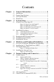
Contents Chapter 1 General Information ........................................2 1.1 1.2 1.3 1.4 Chapter Introduction ....................................................................... 2 General Specifications....................................................... 2 LCD Specifications ........................................................... 5 Dimensions........................................................................ 6 2 System Setup.....................................................
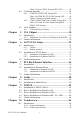
Table 4.3:Clear CMOS / External RTC (JP1) .............. 24 4.4 COM-port Interface......................................................... 24 4.4.1 4.4.2 4.5 VGA Interface ................................................................. 28 4.5.1 Chapter Introduction ..................................................................... 30 5.1.1 5.2 Introduction ..................................................................... 32 6.1.1 6.1.2 6.2 6.3 Installation for Windows 98/ME ............
10.1.3 Environmental Specifications ....................................... 47 10.2 Installation of Touchscreen Drivers ................................ 47 10.2.1 Inst. of Resistive T/S driver for Windows 98/ME ........ 48 10.2.2 Inst. of Resistive T/S driver for Windows 2000/XP..... 49 10.2.3 Inst. of Infrared T/S driver for Windows 2000/XP....... 49 10.3 Further Information ......................................................... 49 Appendix A Programming the Watchdog Timer .............52 A.
PPC-V106 User Manual xii
CHAPTER 1 General Information This chapter gives background information on the PPC-V106 panel PC.
Chapter 1 General Information 1.1 Introduction PPC-V106 is fanless and comes with a VIA Eden low-power CPU for higher reliability and performance. The ruggedized aluminum enclosure without ventilation holes makes PPC-V106 waterproof and dust proof. A variable power source suits vehicles such as forklifts and trucks, which typically operate anywhere from 12 to 48 VDC. PPC-V106 provides 10/100Base-T Ethernet, and expansion ability for wireless transmissions, ex : 802.11g/b, GPS, GPRS and CDMA..etc..
Standard PC functions • CPU: Embedded VIA Eden 800 MHz CPU • BIOS: Award 256 KB Flash BIOS, supports Plug & Play, APM • System Chipset: VIA CLE266 and VT8235 CD • Front side bus: 133 MHz • System Memory: Two 184-pin DIMM sockets, accepts up to 2 GB DDR 266 SDRAM • PCI bus master IDE interface: Supports two connectors. Each connector has one channel and supports two IDE devices. Each channel supports PIO modes 0 ~ 4, DMA mode 0 ~ 2, and Ultra DMA 33/66/ 100 simultaneously.
Audio function • Chipset: Integrated in VT8235CD South Bridge • Audio controller: AC97 Ver. 2.0 compliant interface, Multi stream Direct sound and Direct Sound 3D acceleration • Stereo sound: 18-bit full-duplex codec • Audio interface: Line out PCI bus Ethernet interface • Chipset: Realtek RTL8100C PCI local bus Ethernet controller • Ethernet interface: Full compliance with IEEE 802.3u 100Base-T and 10 Base-T specifications. Includes software drivers and boot ROM.(Support both RPL and PXE).
Environment • Operating Temperature: 0 ~ 45° C (32 ~ 122° F) • Storage Temperature: -20 ~ 60° C • Relative Humidity: 10 ~ 95% @ 40° C (non-condensing) • Shock: 10 G peak acceleration (11 msec duration) • Certifications: EMC: CE, FCC. Safety: UL1950. • Vibration: 5 ~ 500 Hz 1 G RMS Random vibration n (operating with HDD) 1.3 LCD Specifications • Display type: 10.4" TFT LCD • Max. resolution: 800 x 600 • Colors: 256 K • Dot size (mm): 0.264 x 0.
1.
CHAPTER 2 System Setup This chapter details system setup on the PPC-V106 Panel PC.
Chapter 2 System Setup 2.1 A Quick Tour of the Panel PC Before you start to set up the panel PC, take a moment to become familiar with the locations and purposes of the controls, drives, connectors and ports, which are illustrated in the figures below. When you place the panel PC upright on the desktop, its front panel appears as shown in Figure 2-1 Figure 2.1: Front View of the Panel PC When you look at the right side of the panel PC, you will see the holes for mounting as shown in Fig. 2-2. Figure 2.
When you turn the Panel PC around and look at its rear cover, you will find VESA standard holes and others for mounting. There are no ventilation holes, as shown in Figure 2-3. Figure 2.3: Rear Side View of the Panel PC The I/O section is at the bottom of the panel PC, as shown in Fig. 2-4. 1 2 3 Figure 2.
2.2 Installation Procedures 2.2.1 Connecting the Power Cord There are two kinds of power supplies for the PPC-V106 series, AC and DC. For AC model : The Panel PC can only be powered by an AC electrical outlet (100 ~ 250 volts, 50 ~ 60 Hz). Be sure to always handle the power cords by holding plug ends only. Follow these procedures in order: 1. Connect the female end of the power cord to the AC inlet of the panel PC. 2. Connect the 3-pin male plug of the power cord to an electrical outlet.
2.3 Running the BIOS Setup Program Your panel PC is likely to have been properly set up and configured by your dealer prior to delivery. You may still find it necessary to use the panel PC's BIOS (Basic Input-Output System) setup program to change system configuration information, such as the current date and time or your type of hard drive. The setup program is stored in read-only memory (ROM).
2.4 Installing System Software Recent releases of operating systems from major vendors include setup programs which load automatically and guide you through hard disk preparation and operating system installation. The guidelines below will help you determine the steps necessary to install your operating system on the panel PC hard drive. Note: Some distributors and system integrators may have already pre-installed system software prior to shipment of your panel PC.
2.5 Installing the Drivers After installing your system software, you will be able to set up the Ethernet, SVGA, audio, and touchscreen functions. All the drivers except the CD-ROM drive driver are stored in a CD-ROM disc entitled "Drivers and Utilities." The CD-ROM drive driver is stored in a floppy disk. Both the CD-ROM and the floppy disk can be found in your accessory box.
PPC-V106 User Manual 14
CHAPTER 3 Hardware and Peripheral Installation This chapter details the installation of the PPC-V106 panel PC hardware. Sections include: • Overview of Hardware Installation and Upgrading • Installing the 2.
Chapter 3 Hardware and Peripheral Installation 3.1 Overview of Hardware Installation and Upgrading The panel PC consists of a PC-based computer that is housed in a ruggedized aluminum enclosure. Any maintenance or hardware upgrades can be completed after removing both panels.. Warning! Do not remove the ruggedized aluminum covers until you have verified that no power is flowing within the panel PC. Power must be switched off and the power cord must be unplugged.
2. Place the HDD inside the HDD bracket and tighten four screws (#1) from both sides of the HDD bracket. HDD (Bottom up) Pin 1 1 3. The HDD cable (1 x 44-pin to 1 x 44-pin) is next to the HDD bracket. Connect the HDD cable to the HDD. Make sure that the red wire corresponds to Pin 1 on the connector, which is labelled on the board. Plug the other end of the cable into the HDD, with Pin 1 on the cable corresponding to Pin 1 on the HDD. 3.
3.4 Installing the Universal Arm 1. Press latches at the same time and then rotate support-1 until you can see both of the screw holes. 2. Rotate support-2 until the angle is the same as support-1. 3. Use four M4x8L screws and attach the U-Arm with the PPC-V106. The 4 stainless screws can be found in the universal arm's box. 4. Use latches adjust the angle of PPC-V106 (every 14.4° on 360°). Note: Support-1 can be on the right or left.
CHAPTER 4 Jumper Settings and Connectors This chapter tells how to set up the panel PC hardware, including instructions on setting jumpers and connecting peripherals, switches and indicators. Be sure to read all the safety precautions before you begin the installation procedures.
Chapter 4 Jumper Settings and Connectors 4.1 Setting Jumpers You can configure your panel PC to match the needs of your application by setting jumpers. A jumper is the simplest kind of electrical switch. It consists of two metal pins and a small metal clip (often protected by a plastic cover) that slides over the pins to connect them. To “close” a jumper, you connect the pins with the clip. To “open” a jumper you remove the clip. Sometimes a jumper will have three pins, labeled 1, 2, and 3.
4.1.1 Jumpers and Switches The motherboard of the panel PC has a number of jumpers that allow you to configure your system to suit your applications. The table below lists the function of each of the boardís jumpers. Table 4.1: Jumpers and their functions Label Function JP1 CMOS clear for external RTC JP2 LCD power connector JP3 COM1 / COM2/ COM3 pin 9 output type setting JP4 COM1 / COM2/ COM3 pin 9 output type setting JP5 COM2 RS232/422/485 setting SW1 Panel type setting (Reserved) 4.1.
4.1.3 Connectors Onboard connectors link the panel PC to external devices such as hard disk drives or floppy drives. The table below lists the function of each of the board ís connectors. Table 4.
4.1.4 Locating Connectors Figure 4.2: Locating Connectors on the PPC-V106 Motherboard 4.2 CPU Installation The CPU is embedded on the motherboard, so there are no settings for frequency ratio or voltage.
4.3 CMOS Clear for External RTC (JP1) Warning: To avoid damaging the computer, always turn off the power supply before setting “Clear CMOS”. Set the jumper back to “Normal operation” before turning on the power supply. Table 4.3: Clear CMOS / External RTC (JP1) *Normal operation (default) 1 2 Clear CMOS 3 1 2 3 4.4 COM-port Interface The panel PC provides three serial ports: COM1, COM 3 : RS-232 and COM2: RS-232/422/485 (in one COM port connector). 4.4.
The IRQ and the address ranges for COM1, COM2, COM3 and COM4 are fixed. However, if you wish to disable the port or change these parameters later you can do this in the system BIOS setup. The table overleaf shows the default settings for the panel PC’s serial ports. COM1 and COM2 are one set. You can exchange the address range and interrupt IRQ of COM1 for the address range and interrupt IRQ of COM2. After exchanging: COM1's address range is 2F8 ~ 2FF and its request IRQ is IRQ3.
4.4.2 COM1/COM2/COM3/ Pin 9 Output Setting (JP4) Table 4.6: COM1/2/3 Pin 9 Output Setting(JP4) Normal (default) 11 9 7 5 3 1 12 10 8 6 4 2 11 9 7 5 3 1 12 10 8 6 4 2 11 9 7 5 3 1 12 10 8 6 4 2 +5 V output +12 V output NOTE: Pins 1, 3 and 5 are for COM1 Pins 2, 4 and 6 are for COM2 Pins 7, 9 and 11 are for COM3 When enabling this function, you should remove a jumper from JP3 as shown in table 4.7.
Table 4.7: JP3 Setting Normal (default) Remove jumper from pin 1 and 2 to make pin 9 on COM1 a power output. Remove jumper from pin 3 and 4 to make pin 9 on COM2 a power output. Remove jumper from pin 5 and 6 to make pin 9 on COM3 a power output.
4.5 VGA Interface The panel PC's AGP VGA interface can drive conventional CRT displays. It is also capable of driving a wide range of flat panel displays, including electroluminescent (EL), gas plasma, passive LCD and active LCD displays. The board has two connectors to support these displays simultaneously: one for standard CRT VGA monitors, and one for flat panel displays. Pin assignments for the flat panel display connector, backlight connector and other related connectors are shown in Appendix C. 4.5.
CHAPTER 5 VIA Chipset This chapter provides information on Intel chipset configuration • Introduction • Further information
Chapter 5 VIA Chipset 5.1 Introduction The PPC-V106 uses the combination of VIA CLE266 north bridge and VT8235 CD south bridge. The VIA CLE266 chipset is an innovative integrated graphics chipset developed with DDR266 memory and optimized to support the VIA C3 and VIA Eden Series processors, adding intelligence to help manage and prioritize multiple threads received from the microprocessor.
CHAPTER 6 AGP SVGA Setup • Introduction • Installation of SVGA Driver - for Windows 98/ME - for Windows 2000/XP • Further Information
Chapter 6 AGP SVGA Setup 6.1 Introduction The PPC-V106 has an onboard integrated VGA chipset The specifications and features are described as follows: 6.1.1 Chipset The VIA CLE266 boasts a complete integrated VIA 128-bit 2D/3D graphics engine with a high quality video processing unit including MPEG-2 decoding, video scaling and Alpha Blending. 6.1.2 Display memory The integrated VGA chipset can support 8 / 16 / 32 / and 64 MB frame buffer using system memory. 6.
6.2.1 Installation for Windows 98/ME 1. Click the 'Start' button in the task bar, click 'Run' and then select 'Setup.exe' from D:\PPC-S154\845G Graphics Driver\WIN9X_ME\Setup.exe. The Install dialog will appear. 2. Click 'Next' to continue. 3. Read License Agreement and click "Yes" to proceed. 4. When the 'Setup COMPLETE' message appears click 'Finish' to restart PPC-V106. 5. After the system reboot, the screen show "Insert Disk", click "OK" 6. click "browse" 6.2.
PPC-V106 User Manual 34
CHAPTER 7 PCI Bus Ethernet Interface This chapter provides information on Ethernet configuration.
Chapter 7 PCI Bus Ethernet Interface 7.1 Introduction The PPC-V106 is equipped with a high performance 32-bit Ethernet chipset which is fully compliant with IEEE 802.3 100 Mbps CSMA/CD standards. It is supported by major network operating systems. It is also both 100Base-T and 10Base-T compatible. The Ethernet port provides a standard RJ-45 jack. The network boot feature can be utilized by incorporating the boot ROM image files for the appropriate network operating system.
7.2.1 Installation for Windows 98/ME 1. If the Operating System's New Hardware Wizard prompts you with "New Hardware Found" for the "PCI Ethernet Controller", you should click "Next" until "Finish" is clicked, without specifying location of the driver. You will see "PCI Ethernet Controller" in the Device Manager. 2. You can then install or update the NDIS driver with the "setup" or "setup -s" command: a) setup: The InstallShield will prompt you with steps to install or upgrade the driver.
7.3 Further Information Realtek website: www.realtek.com.tw Advantech website: www.advantech.
CHAPTER 8 2 Audio • Introduction • Installation of Audio Driver
Chapter 8 Audio 8.1 Introduction The ALC202 is an 18-bit, full duplex AC'97 2.2 compatible stereo audio CODEC designed for PC multimedia systems, including host/soft audio and AMR/CNR based designs. The ALC202 AC'97 CODEC supports multiple CODEC extensions with independent variable sampling rates and built-in 3D effects. 8.2 Installation of Audio Driver Before installing the audio driver, please take note of the procedures detailed below.
CHAPTER 9 USB 2.0 This chapter describes how to install the USB 2.
Chapter 9 USB 2.0 9.1 Installation of USB 2.0 Driver Before installing the audio driver, please take note of the procedures detailed below. You must know which operating system you are using in your PPC-V106, and then refer to the corresponding installation procedure Important : The following Windows illustrations are examples only. You must follow the instructions and pay attention to the instructions that appear on your screen. Note: The CD-ROM drive is designated as "D" throughout ths chapter. 9.
9.3 Driver Installation for Windows 2000 1. Install Service Pack 3 or above before running the setup program. 2. Open the Device Manager and check if there is a “Universal Serial Bus (USB) Controller” under “Other devices”. 3. Execute the setup program by double click on the “SETUP.exe” file in \PPC-V106\USB2.0 4. The screen shows the VIA Software License Agreement. Please read it FIRST and press “Yes” if wish to further proceed with the driver installation. 5. Press “Next”. 6.
9.4 Driver Installation for Windows ME / 98 / 98SE 1. Open the Device Manager and check if there is a yellow exclamation mark on any one of the “VIA Tech 3038 PCI to USB Universal Host Controller” items. 2. Execute the setup program by double click on the “SETUP.exe” file in \PPC-V106\USB2.0 3. Press “Next”. 4. Select “Install USB Driver” and press “Next”. 5. Press “Finish” and this will RESTART the computer system. Please remember to SAVE all files before clicking the “Finish” button.
CHAPTER 10 Touchscreen • Introduction • Installation of Touchscreen Drivers - for Windows 98/ME - for Windows 2000/XP
Chapter 10 Touchscreen 10.1 Introduction 10.1.1 General information There are two kinds of touch screens for the PPC-V106 series, one is resistive touch screens, the other for infrared touch screens. The resistive touch screen incorporates advanced second-generation resistive, impact-resistant technology, which allows 75% light transmission. There is also an antiglare surface for greatly enhanced visual resolution. It also has new and improved scratch-resistant features.
10.1.
10.2.1 Installation of Resistive T/S driver for Windows 98/ME To install the software to PPC-V106, your PPC-V106 must have Windows 98/Me system running and installed PenMount Series Interface control board already. If you have an older version of PenMount Windows 98/Me driver installed in your PPC-V106, please remove it first. 1. You will find out "Unknown Device" when start the system, please choose "Cancel" 2. Select from "D:\PPC-V106\Resistive touchScreen\Windows 98-Me Driver V3.1\setup.
10.2.2 Installation of Resistive T/S driver for Windows 2000/XP To install the software to PPC-V106, your PPC-V106 must have Windows 2000/XP system running and installed PenMount Series Interface control board already. If you have an older version of PenMount Windows 2000/XP driver installed in your PPC-V106, please remove it first. Follow up the steps below to install the PenMount Window 2000/XP driver. 1. Select from "D:\PPC-V106\Resistive touchScreen\Windows 2000XP Driver V4.01\setup.
PPC-V106 User Manual 50
Appendix A Programming the Watchdog Timer The PPC-V106 is equipped with a watchdog timer that resets the CPU or generates an interrupt if processing comes to a standstill for any reason. This feature ensures system reliability in industrial standalone or unmanned environments.
Appendix A Programming the Watchdog Timer A.1 Programming the Watchdog Timer To program the watchdog timer, you must write a program which writes I/ O port address 440 (hex). The output data is a time interval value. The value range is from 01 (hex) to 3F (hex), and the related time interval is from 1 sec. to 63 sec. Data Time Interval 01 1 sec. 02 2 sec. 03 3 sec. 04 4 sec. ï ï ï ï ï ï 3F 63 sec.
;----------------------------------------------------------------------------; Configurate logical device 8, configuration register CRF6 | ;----------------------------------------------------------------------------MOV DX,2EH MOV AL,07H ; point to Logical Device Number Reg.
;-----------------------------------------; Exit extended function mode | ;-----------------------------------------MOV DX,2EH MOV AL,AAH PPC-V106 User Manual 54
Appendix B Pin Assignments This appendix contains information on PPC-V106’s pin assignments.
Appendix B Pin Assignments B.1 Inverter Power Connector (CN10) Table B.1: Inverter power connector (CN10) Pin Signal 1 +12V 2 GND 3 ENAVEE 4 VBR 5 +5 V 1 2 3 4 5 B.2 Internal Speaker Connector (CN14) 1 2 3 4 Table B.
B.3 Floppy Drive Connector (CN16) Reserved Table B.
B.
B.5 IR Connector (CN8) Reserved 1 2 3 4 5 Pin Signal 1 +5V 2 X 3 IR_RX 4 GND 5 IR_TX B.
B.
B.8 COM1 1 2 3 4 5 6 7 8 9 Pin Signal 1 DCD 2 RxD 3 TxD 4 DTR 5 GND 6 DSR 7 RTS 8 CTS 9 RI B.
B.10 COM3 1 2 3 4 5 6 7 8 9 Pin Signal 1 DCD 2 RxD 3 TxD 4 DTR 5 GND 6 DSR 7 RTS 8 CTS 9 RI B.
B.12 COM 4 Connector (CN 23) Pin Signal 1 DCD 2 DSR 3 RXD 4 RTS 5 TXD 6 CTS 7 DTR 8 RI 9 GND 10 5V 11 GND 12 5V B.
B.14 Parallel Port Connector (CN11) Table B.
B.
PPC-V106 User Manual 66