RMD-1150 series 1U Rackmount display Industrial PC chassis User’s manual
Copyright notice This document is copyrighted, 2000, by Advantech Co., Ltd. All rights are reserved. Advantech Co., Ltd. reserves the right to make improvements to the products described in this manual at any time without notice. No part of this manual may be reproduced, copied, translated or transmitted in any form or by any means without the prior written permission of Advantech Co., Ltd. Information provided in this manual is intended to be accurate and reliable. However, Advantech Co., Ltd.
A Message to the Customer Advantech customer services Each and every Advantech product is built to the most exacting specifications to ensure reliable performance in the harsh and demanding conditions typical of industrial environments. Whether your new Advantech equipment is destined for the laboratory or the factory floor, you can be assured that your product will provide the reliability and ease of operation for which the name Advantech has come to be known. Your satisfaction is our primary concern.
1.1 Safety Instructions, disclaimer, and warranty Note: Read these instructions. Save these instructions for later use. 1. Follow all warnings and instructions marked on the product. 2. Unplug this product from the wall outlet before cleaning. Do not use liquid cleaners or aerosols cleaners. Use a damp cloth for cleaning. 3. Do not use this product near water. 4. Do not place this product on an unstable cart, stand, or table. The product may fall, causing serious damage to the product. 5.
rating. Also ensure that the total of all products plugged into the wall outlet does not exceed 15 amperes. 10. Never push objects of any kind into this product through cabinet slots as they may touch dangerous voltage points or short out parts that could result in a risk of fire or electric shock. Never spill liquid of any kind on the product. 11 .Do not attempt to service this product by yourself, as opening or removing covers may expose you to dangerous voltage points or other risks.
(2) Reduced Air Flow--- Installation of the equipment in a rack should be such that the amount of air flow required for safe operation of the equipment is not compromised. (3) Mechanical Loading--- Mounting of the equipment in the rack should be such that a hazardous condition is not achieved due to uneven mechanical loading.
1.
Two-Console 15.0" TFT LCD display Switch The advanced multi-access RMD switch and RMD-1150F-8 enables you to control multiple computers from one or two locations respectively. There is no interface card or software to configure. Installation is as easy as connecting cables between the RMD switch and your computers. Operation is as simple as entering a hot-key command and navigating through the userfriendly on-screen menu.
1.2.
1.2.3 More features for multi-access • Manage multiple computers from two locations (RMD-1150F-8 only) • Different console access, one by internal touch-pad, or external, may have different types of mouse i.e. generic PS/2 mouse and scroll mouse.
1.3 Configurations RMD-1150F-8 supports 8 computers. For applications with a large number of computers, RMD-1150F-8 can be cascaded to another model of RMD-1150F-8’s family in a Master/slave configuration to support up to 64 computers. Single RMD Switch Configuration In case you need to use multi-access to manage your computer systems, connect a PS/2 keyboard, a PS/2 mouse and a VGA multisync monitor directly to the RMD-1150F-8's external CONSOLE port.
Note: Throughout this manual, RMD-1150F-8 is the Master that has a physical keyboard, mouse and monitor connected to its CONSOLE port. Slave is a RMD-1150F-8 KVM switch family that has its CONSOLE port connected to a RMD-1150F-8's "PC x" port. Slave only exists in cascade configuration.
1.4 Installation External Device Connection The monitor connected to the HD-DB-15 VGA port of a RMD switch CONSOLE must be capable of synchronizing with the computer's video signal. If you are uncertain about the monitor type, please consult the monitor user's manual. Connect a PS/2 mouse and a keyboard to the CONSOLE port marked with a mouse and a keyboard respectively as shown in figure 2. NOTE: Only a PS/2 mouse can be connected to the CONSOLE mouse port.
Determine the channel address of each computer. For computers using a PS/2 mouse, connect the computer's mouse and keyboard cables to the RMD-1150F8's connectors marked with a mouse and keyboard respectively, as shown in figure 3. Figure 1- 3: RMD-1150F-8 computer connection For computers using a serial mouse, connect the DB-9 to miniDIN-6 adapter to the computer mouse port, then use PS/2 cables to connect the mouse to the RMD switch, see figure 4.
Initial Power-Up Make sure all computers and RMD switch are powered down during installation. You must power up the RMD switch before turning on any other devices. • For single RMD switch: 1. Apply a power adapter to the RMD switch. 2. Turn on computers. • For cascade: 1. Apply a power adapter to the switch. 2. Apply power adapters to all Slaves. 3. Turn on computers.
1.5 Operation (OSD (On-Screen-Display) Operation For KVM Switch) Figure 1-5: KVM portion OSD screen illustration 1.5.1 Introduction By hitting the left key twice within two seconds, you may see the 'Hotkey Menu' if it is enabled (an OSD option).
will see a 'KVM MENU' screen showing a list of the computers with corresponding channel addresses, names and status, see figure 5. The channel address of the currently selected computer is displayed in red to the right of the OSD title 'KVM MENU'. The color of a device name is green if it has power and is ready for selection, or the color is white as it has no power. OSD menu updates the color when it is activated. Use the and arrow keys to highlight a computer and the key to select it.
1.5.3 Function key To switch the eye mark " of a computer on or off. First, use the and arrow keys to highlight it, then press to switch its eye mark on or off. If Scan Type is 'Ready PC +"', only the power-on and eye mark selected computers will be displayed sequentially in Scan mode. 1.5.4 Function key To lock a device (a computer or a Slave) from unauthorized access, use Security. Security is effective for only one device (a computer or a Slave).
1.5.5 Function key More functions are available by hitting . A new screen pops up displaying more functions as described below. Most of them are marked with a triangle (#) indicating there are options to choose from. Using the and arrow keys, select the functions and press . Available options will be shown in the middle of the screen. Again, using the and arrow keys to view options then press to select it. You can press to exit at any time.
It is useful if you want to listen to a particular computer's audio signal while operating other computers. The non-volatile memory stores the Audio Stick setting. • Scan Type ": In Scan mode, scan through power-on and eye Ready PC +" mark selected computers. Ready PC: In Scan mode, scan through power-on computers. The non-volatile memory stores the Scan Type setting. • Scan Rate Sets the duration of a computer displayed in Auto Scan mode. The options are 3 seconds, 8 seconds, 15 seconds and 30 seconds.
• Position The position of the selected computer name and/or OSD status displayed on screen during operation. The actual display position shifts due to different VGA resolution, the higher the resolution the higher the display position. The non-volatile memory stores the Position setting.UL as Upper Left, UR as Upper Right,LL as Lower Left, LR as Lower Right. MI as MIddle. 1.5.6 ESC To exit the OSD, press the key. 1.5.
and the second one is the channel address of the Slave (1~8). Left Ctrl + left Ctrl + 7 Selects a computer connected to port 7 of the RMD switch. Left Ctrl + left Ctrl + 6 + C Selects a computer connected to port C of a Slave connected to port 6 of the RMD switch.
The RMD switch sends one to four beeps indicating scan intervals of 3, 8, 15 and 30 seconds respectively. • To adjust keyboard typematic rate (characters/sec), this setting over-rides that of BIOS and any operating system: left Ctrl + left Ctrl + F4 The RMD switch generates 1 to 4 beeps corresponding to 10, 15, 20 and 30 characters/sec respectively. • Audio Stick An optional multimedia module can be LINKed to the back of each RMD-1150F-8 for selecting microphone and stereo speaker signals.
4. POWER STAND-BY MODE LED: Show LCD system in the power stand-by model. 5. Power on LED: Show LCD system in the power on model. The Control Key Description 1. MENU : Press any key to MENU 2. DOWN: Move to the next item 3. UP : Move to the previous item 4. + : Increment control 5. - : Decrement control 6. LCD POWER : Power Switch 7.
BRIGHTNESS : Adjust the backlight bulb intensity showing on the screen by pressing "+"or"-" CONTRAST: The operation is the same as the brightness by way of adjusting "+ " or "-" to change the brightness value HORIZONTAL POSITION: Push to move the screen to the left or right VERTICAL POSITION: Push to move the screen up or down H-SCALING: Push to increase or decrease the Horizontal screen size (not available) AUTO ADJUSTMENT: Press "+" or "-" to move the AUTO adjustment, find the optimal.
OSD TIMER: Press "+" or "-" to adjust the OSD Showing time.
1.7 Cascaded Configuration 1.7.1 General Note: Before connecting a device (a computer or a Slave) to the RMD-1150F-8, you must turn off the device. The RMD1150F-8 must also have equal or more 'PC x' ports than that of the Slave. The ports labeled "PC 1"~"PC 8" can be connected to either a computer or a Slave's CONSOLE port, as shown in figure 8. A power adapter with DC 12V/3.5A output rating must be connected to the RMD-1150F-8, it supply either LCD display and switch to work.
• For system check by OSD After connection completes, you should re-activate the KVM portion OSD menu to check if the RMD-1150F-8 recognizes the Slaves. A triangle mark (!) is placed to the right of the channel name indicating the port is connected to a Slave not a computer. A number to the left of the triangle mark indicates the Slave model, i.e. 8! for KNV108 or KNV108D. • Change Configuration while Running Devices at any 'PC x' port can be changed at any time after initial power-up.
The LCD Products listed on this document are not suitable for use of aerospace equipment, submarine cables, nuclear reactor control system and life support systems. If customers intend to use these LCD products for above application or not listed in "Standard" as follows, please contact our sales people in advance. Standard: Computer, Office equipment, Communication equipment, Test and Measurement equipment, Machine tool, Industrial robot, Audio and Visual equipment, Other consumer products.
1.8 Troubleshooting Note:Ensure that all cables are well seated. Check that keyboard/mouse cables are not swapped. Label and bundle the cables for each computer to avoid confusion when connected to RMD-1150 switch.
Symtoms Possible causes Solutions No OSD screen -No power to RMD swi tch. -Loose moni tor connecti on -Moni tor not multi -sync -Establi sh power by turni ng on computers, wai t, press left C TRL keys several ti mes. -Reconnect moni tor. -Use multi -sync moni tor Hori zontal bli nki ng li nes appears i n LC D -Incorrect resoluti on. -Incorrect V-Frequency -Adjust to 1024x 768 resoluti on. -Adjust to di fferent VFrequency (Hz) Keyboard error on boot -Loose keyboard connecti on .
Symtoms Possible causes Solutions Double OSD images at cascade configuration .Improper slave connection procedure. -Remove any possible power supply to the Slave (unplug all cables), before connecting it to the RMD switch. OSD menu is not at the proper position .OSD menu has fixed resolution and its size varies due to computer VGA resolution changes. -Use :More\Position to select UL or UR. OSD menu may appear near the middle of the screen when LL or LR is selected.
C ondition C heckpoint Pi cture doesn't appear. -C heck to make sure the si gnal cable i s fi rmly seated i n the socket -C heck to see i f the computer system Power i s ON -C heck that the bri ghtness control i s at the appropri ate posi ti on, not at the mi ni mum. -Turn off your moni tor. Hold down + and - Si multaneously whi le turni ng on your moni tor. Thi s wi ll reset your moni tor and " all mode reset" Wi ll appear. Screen i sn't synchroni zed.
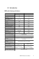
Compatible modes: The display has been designed to be compatible with a variety of computers. The Table below describes the display timing of the compatible modes.
Resolution Modes: Mode Resolution H-Freq.(KHz ) V-Freq.(Hz ) Model 1 640x350 31.47 70 Model 2 640x400 24.82 56 Model 3 640x400 31.47 70 Model 4 640x480 31.47 60 Model 5 640x480 35 67 Model 6 640x480 37.86 72 Model 7 640x480 37.5 75 Model 8 640x480 43.27 85 Model 9 720x400 31.47 70 Model 10 720x400 37.92 85 Model 11 800x600 35.15 56 Model 12 800x600 37.87 60 Model 13 800x600 48.07 72 Model 14 800x600 46.87 75 Model 15 800x600 53.
Limited Warranty IN NO EVENT SHALL THE DIRECT VENDOR'S LIABILITY FOR DIRECT OR INDIRECT, SPECIAL, INCIDENTIAL OR CONSEQUENTIAL DAMAGES, LOSS OF PROFIT, LOSS OF BUSINESS, OR FINANCIAL LOSS WHICH MAY BE CAUSED BY THE USE OF THE PRODUCT EXCEEDS THE PRICE PAID FOR THE PDOCUDT.
RMD-1150 Series User's Manual 37
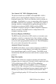
- TechNote Subject: Automatic serial mouse and PS/2 mouse conversion Symptom: PS/2 mouse does not work at all. Cause: As per IMB PC spec, there are two pins (# 2 and # 6) in PS/2 mouse connector left unconnected. These two pins are used for serial mouse identification and communication. However, very few motherboard designers ignore the spec and ground these pins. Therefore, when that computer boots up, the NovaView mistakenly identifies the mouse to be serial mouse. Solution: 1.