
User Guide


Your ePlatform Partner
User’s Manual for Advantech SOM-A2552 series module V1.00
12
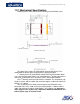
1.2.1 Mechanical Specification
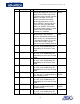
Following figure shows the mechanical drawing of SOM-A2552 series.
The above figure shows the SOM-A2552 mechanical drawing. Users
could follow the above figure to implement the layout procedure.
1
st
drawing shows the SOM-A2552 module PCB mechanical data. When
users enter the layout procedure, user could follow the 1
st
drawing to place the
connector. SOM-A2552 series PCB form factor is 68mm*68mm*68mm.
The 2
nd
drawing shows the PCB thickness limitation. The component side
height is 2.8mm, and the solder side maximum height is 3.00mm and the PCB
thickness is 1.00mm.
The 3
rd
drawing shows allied mechanical data of SOM-A2552 series
board and CSB. Users could see that the matting height is 3.00mm and the
solder side maximum height of SOM-A2552 is also 3.00mm. So, Advantech
don’t suggest users to place any components between SOM module and
CSB in layout stage. It could be short!