EH-2101W Broadband Wireless Gateway WiFi Compliant Wireless Access Point Broadband Internet Access 4-Port Switching Hub Dial-in RAS Print Server User Manual i
TABLE OF CONTENTS CHAPTER 1 INTRODUCTION ............................................................................................. 1 UniGateway EH-2101W Features.................................................................................... 1 Package Contents .............................................................................................................. 4 Physical Details..................................................................................................................
Options ............................................................................................................................. 73 Printer Port...................................................................................................................... 75 MAC Address .................................................................................................................. 76 Routing .......................................................................................................
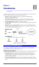
Chapter 1 Introduction 1 This Chapter provides an overview of the UniGateway EH-2101W's features and capabilities. Congratulations on the purchase of your new UniGateway EH-2101W. The UniGateway EH2101W is a multi-function device providing the following services: • Wireless LAN Access Point (base station) for equipment compliant with the • Shared Broadband Internet Access via an DSL or Cable modem on the WAN • 4-Port Switching Hub for 10BaseT or 100BaseT connections.
UniGateway EH-2101W User Manual • PPPoE and PPTP Support. The Internet (WAN port) connection supports PPPoE • Analog Modem and ISDN TA Support. If you don't yet have Broadband Internet • Fixed or Dynamic IP Address. On the Internet (WAN port) connection, the UniGate- (PPP over Ethernet) and PPTP (Peer-to-Peer Tunneling Protocol), as well as "Direct Connection" type services.
Introduction Network Printer • Shared Printer (Network Printer). A printer connected to the UniGateway EH2101W's parallel port can be shared by all PCs on the LAN or WLAN. • Multiple OS Support. Clients may use any of the following operating systems: • • Windows 95/98/ME • Windows NT 4.0, 2000, or XP. • Apple Macintosh • Unix Multi-protocol Support. The following printing methods are supported: • Windows peer-to-peer printing over TCP/IP, using the supplied port driver.
UniGateway EH-2101W User Manual width and so many resources that Internet access becomes unavailable. The UniGateway EH-2101W incorporates protection against DoS attacks. Package Contents The following items should be included: • The UniGateway EH-2101W Unit • Wireless PCMCIA Card • Power Adapter • Quick Installation Guide • CD-ROM containing the on-line manual and Print Port Driver for Windows. If any of the above items are damaged or missing, please contact your dealer immediately.
Introduction Wireless On - Wireless connection available; Wireless Access Point is ready for use. Off - No Wireless connection available. Flashing - Data is transmitted or received via the Wireless access point. This includes "network traffic" as well as user data. WAN On - Connection to the modem attached to the WAN (Internet) port is established. Flashing - Data is being transmitted or received via the WAN port. COM Off - Idle or no active device connected to the serial (RS232) port.
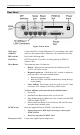
UniGateway EH-2101W User Manual Rear Panel Figure 2: Rear Panel WAN port (10BaseT) Connect the DSL or Cable Modem here. If your modem came with a cable, use the supplied cable. Otherwise, use a standard LAN cable. DIP switches Refer to the following table. Serial Port RS232 Serial Port. If you have an analog modem or ISDN TA, connect it here. Reset Button This button has three (3) functions: • Reboot. When pressed and released, the UniGateway EH2101W will reboot (restart).
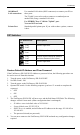
Introduction 10/100BaseT LAN connections Use standard LAN cables (RJ45 connectors) to connect your PCs to these ports. The "Uplink" port can be used to connect to a standard port on another Hub, using a standard LAN cable. Use EITHER "Port 1" OR the "Uplink" port. You can NOT use both. Standard parallel printer port. If you wish to share a printer, connect it here. Printer Port DIP Switches DIP Switch Setting Description 1=off 2=off Normal Operation. 1=off 2=on DHCP Server function disabled.
2 Chapter 2 Installation This Chapter covers the physical installation of the UniGateway EH-2101W. Requirements • Network cables. Use standard 10/100BaseT network (UTP) cables with RJ45 connectors. • TCP/IP protocol must be installed on all PCs.
Installation For best Wireless reception and performance, the Access Point should be positioned in a central location with minimum obstructions between the Access Point and the PCs. Also, if using multiple Access Points, adjacent Access Points should use different Channels. 2. Insert Wireless PCMCIA card Ensuring the supplied Wireless PCMCIA card is the right way up, insert it into the slot on the rear. Push it firmly until it clicks into position. 3.
3 Chapter 3 Setup This Chapter provides Setup details of the UniGateway EH-2101W. Overview This chapter describes the setup procedure for: • Internet Access • LAN configuration • Wireless setup • Assigning a Password to protect the configuration data. PCs on your local LAN may also require configuration. For details, see Chapter 4 - PC Configuration. Other configuration may also be required, depending on which features and functions of the UniGateway EH-2101W you wish to use.
Setup Configuration Program The UniGateway EH-2101W contains an HTTP server. This enables you to connect to it, and configure it, using your Web Browser. Your Browser must support JavaScript. The configuration program has been tested on the following browsers: • Netscape V4.08 or later • Internet Explorer V4 or later Preparation Before attempting to configure the UniGateway EH-2101W, please ensure that: • Your PC can establish a physical connection to the UniGateway EH-2101W.
UniGateway EH-2101W User Manual If you can't connect If the UniGateway EH-2101W does not respond, check the following: • The UniGateway EH-2101W is properly installed, LAN connection is OK, and it is powered ON. You can test the connection by using the "Ping" command: • Open the MS-DOS window or command prompt window. • Enter the command: ping 192.168.0.
Setup Setup Wizard The first time you connect to the UniGateway EH-2101W, the Setup Wizard will run automatically. (The Setup Wizard will also run if the UniGateway EH-2101W's default setting are restored.) 1. Start the Wizard, and step through it until finished. • 2. You will need to know the type of Internet connection service used by your ISP. • The common connection types are explained in the tables below.
UniGateway EH-2101W User Manual Other Modems (e.g. Broadband Wireless) Type Details ISP Data required Dynamic IP Address Your IP Address is allocated automatically, when your connect to you ISP. None. Static (Fixed) IP Address Your ISP allocates a permanent IP Address to you. IP Address allocated to you. Home Screen After finishing the Setup Wizard, you will see the Home screen. When you connect in future, you will see this screen when you connect. An example screen is shown below.
Setup LAN Screen Use the LAN link on the main menu to reach the LAN screen An example screen is shown below. Figure 5: LAN Screen Data - LAN Screen TCP/IP IP Address IP address for the UniGateway EH-2101W, as seen from the local LAN. Use the default value unless the address is already in use or your LAN is using a different IP address range. In the latter case, enter an unused IP Address from within the range used by your LAN. Subnet Mask The default value 255.255.255.
UniGateway EH-2101W User Manual DHCP What DHCP Does A DHCP (Dynamic Host Configuration Protocol) Server allocates a valid IP address to a DHCP Client (PC or device) upon request. • The client request is made when the client device starts up (boots). • The DHCP Server provides the Gateway and DNS addresses to the client, as well as allocating an IP Address. • The UniGateway EH-2101W can act as a DHCP server. • Windows 95/98/ME and other non-Server versions of Windows will act as a DHCP client.
Setup Wireless Screen The Wireless Access Point settings must match the other Wireless stations. To change the UniGateway EH-2101W's default settings for the Wireless Access Point feature, use the Wireless link on the main menu to reach the Wireless screen. An example screen is shown below. Figure 6: Wireless Screen Data - Wireless Screen Identification Regulatory Domain It is illegal to use this device in any location outside of the regulatory domain.
UniGateway EH-2101W User Manual WEP data encryption • WEP (Wired Equivalent Privacy) status will display "Enabled" or "Disabled", depending on whether WEP is being used. If used, data is Encrypted before being transmitted, making communication more secure. • Click the "Configure WEP" button to access the WEP sub-screen, and view or change the WEP settings. • All Wireless Stations - All wireless stations can use the access point to access your LAN.
Setup WEP Screen This screen is accessed by clicking the "Configure WEP" button on the Wireless screen. An example WEP screen is shown below. Note that in IE, the "Key Table" is only displayed when required. Figure 7: WEP Screen Data - WEP Screen WEP Data Encryption Authentication Type Select the appropriate value - "Open System" or "Shared Key". Check your Wireless card's documentation to see what method to use. Some Wireless cards do not support both methods.
UniGateway EH-2101W User Manual table (all entries identical). 128 Bit Encryption • If selected, data is encrypted using the key before being transmitted. The receiving station must be set to use 128 Bit Encryption, and have the same Key value. Otherwise, it will not be able to decrypt the data. • Key - Enter the key value you wish to use. Other stations must have the same key. Password Screen The password screen allows you to assign a password to the UniGateway EH-2101W.
Chapter 4 PC Configuration 4 This Chapter details the PC Configuration required on the local ("Internal") LAN. Overview For each PC, the following may need to be configured: • TCP/IP network settings • Internet Access configuration • Printer setup • Wireless configuration Windows Clients This section describes how to configure Windows clients for: • Internet access via the UniGateway EH-2101W • Sharing the Printer connected to the UniGateway EH-2101W.
Checking TCP/IP Settings - Windows 9x/ME 1. Select Control Panel - Network. You should see a screen like the following: Figure 10: Network Configuration 2. 3. Select the TCP/IP protocol for your network card. Click on the Properties button. You should then see a screen like the following. Figure 11: IP Address (Win 95) 4. Ensure your TCP/IP settings are correct, as follows: Using DHCP To use DHCP, select the radio button Obtain an IP Address automatically. This is the default Windows settings.
PC Configuration • On the Gateway tab, enter the UniGateway EH-2101W's IP address in the New Gateway field and click Add, as shown below. Your LAN administrator can advise you of the IP Address they assigned to the UniGateway EH-2101W. Figure 12: Gateway Tab (Win 95/98) • On the DNS Configuration tab, ensure Enable DNS is selected. If the DNS Server Search Order list is empty, enter the DNS address provided by your ISP in the fields beside the Add button, then click Add.
Checking TCP/IP Settings - Windows 2000: 1. 2. Select Control Panel - Network and Dial-up Connection. Right click the Local Area Connection icon and select Properties. You should see a screen like the following: Figure 14: Network Configuration (Win 2000) 3. 4. Select the TCP/IP protocol for your network card. Click on the Properties button. You should then see a screen like the following.
PC Configuration Figure 15: TCP/IP Properties (Win 2000) 5. Ensure your TCP/IP settings are correct: Using DHCP To use DHCP, select the radio button Obtain an IP Address automatically. This is the default Windows setting. Restart your PC to ensure it obtains an IP Address from the UniGateway EH-2101W. Using a fixed IP Address ("Use the following IP Address") If your PC is already configured, check with your network administrator before making the following changes.
Checking TCP/IP Settings - Windows XP 1. 2. Select Control Panel - Network Connection. Right click the Local Area Connection and choose Properties. You should see a screen like the following: Figure 16: Network Configuration (Windows XP) 3. 4. Select the TCP/IP protocol for your network card. Click on the Properties button. You should then see a screen like the following.
PC Configuration Figure 17: TCP/IP Properties (Windows XP) 5. Ensure your TCP/IP settings are correct. Using DHCP To use DHCP, select the radio button Obtain an IP Address automatically. This is the default Windows settings. Restart your PC to ensure it obtains an IP Address from the UniGateway EH-2101W. Using a fixed IP Address ("Use the following IP Address") If your PC is already configured, check with your network administrator before making the following changes.
Internet Access To configure your PCs to use the EH-2101W for Internet access: • Ensure that the DSL modem, Cable modem, or other permanent connection is functional. • Use the following procedure to configure your Browser to access the Internet via the LAN, rather than by a Dial-up connection. For Windows 9x/2000 1. 2. 3. 4. 5. 6. 7. Select Start Menu - Settings - Control Panel - Internet Options. Select the Connection tab, and click the Setup button.
PC Configuration Printer Setup for Windows The EH-2101W provides printing support for 2 methods for printing from Windows: • Print Port Driver. After installing the Print Port Driver, Windows users can print directly to the EH-2101W. Print jobs are spooled (queued) on each PC. The supplied Print Port Driver supports Windows 95/98, Windows ME, Windows NT4.0, Windows 2000 and Windows XP. • LPD/LPR Printing. If using Windows NT 4.0 Server or Windows 2000 Server, LPD/LPR printing can be used.
Under Windows 95, if you see the following error message, either install Internet Explorer 4 or later, or follow the procedure in the "Trouble Shooting - Printing" section of Appendix A. 7. 8. A pop-up message will inform you if the port has been created successfully, and then the Windows Add Printer wizard will start. • Select the correct Printer Manufacturer and Model, or use the "Have Disk" option if appropriate. • If desired, change the Printer name so it indicates the device used (e.g.
PC Configuration Figure 19: Print Port Configuration Items shown on this screen are as follows: Port If desired, click Browse to select a different device. (The Select Device Port button is provided to allow this software to work with multi-port models.) The Port Name is shown in the Printer's Properties. Banner Retry Interval Check this option to print a banner page before each print job. • If using a PostScript Printer, check the PostScript box. • The User Name will be printed on the banner page.
LPD/LPR Printing LPD/LPR printing can be used with Windows NT 4.0 Server or Windows 2000. No software needs to be installed on client PCs. Windows NT 4.0 Server Configuration To use LPD printing, Microsoft TCP/IP Printing must be installed and enabled. This can be checked using Start-Settings-Control Panel-Network - Services. To install LPD printing using the EH-2101W, follow this procedure: 1. 2. 3. 4. 5. 6. 7. 8. 9. Go to Start-Settings-Printer and invoke the Add Printer wizard.
PC Configuration Windows 2000 Server Configuration The LPD/LPR Port is not enabled by default. To enable it, use this procedure: 1. 2. In Control Panel, select Add/Remove Programs, then Windows Components. Select Other Network File and Print Services, then click the Details button. Figure 20: Adding LPD/LPR Port (Win 2000) 3. 4. Enable Print Services for Unix, and click OK. Click Next and complete the Wizard. Adding the Printer 1. 2. 3. Open your Printers folder, and start the Add Printer Wizard.
Figure 21: Windows 2000: Select Port 4. 5. 6. 7. 8. In the Dialog requesting Name or Address of server providing lpd, enter the IP address of the EH-2101W. For Name of printer or print queue on that server, enter L1 Click OK, and then Next, and continue the Wizard. At the Select Sharing screen, select the Radio Button for Share As, and enter the shared printer name. The shared name is how other users will see this printer. You should advise client PCs of the Server name and this printer name.
PC Configuration Macintosh Clients From your Macintosh, you can access the Internet via the UniGateway EH-2101W. The procedure is as follows. 1. Open the TCP/IP Control Panel. 2. Select Ethernet from the Connect via pop-up menu. 3. Select Using DHCP Server from the Configure pop-up menu. The DHCP Client ID field can be left blank. 4. Close the TCP/IP panel, saving your settings.
Linux Clients To access the Internet via the EH-2101W, it is only necessary to set the EH-2101W as the "Gateway". Ensure you are logged in as "root" before attempting any changes. Fixed IP Address By default, most Unix installations use a fixed IP Address. If you wish to continue using a fixed IP Address, make the following changes to your configuration. • Set your "Default Gateway" to the IP Address of the EH-2101W. • Ensure your DNS (Name server) settings are correct.
PC Configuration Remote Queue 4. Ln Where n is the Logical Printer number (L1, L2, L3). Logical Printers can be configured on the EH-2101W's Options- Printer Port screen. L1 Save this data, and exit the Printer Configuration. Configuration is now completed, and the printer is now available for use. Other Unix Systems To access the Internet via the EH-2101W. • Ensure the "Gateway" field for your network card is set to the IP Address of the EH2101W.
Chapter 5 Operation and Status 5 This Chapter details the operation of the UniGateway EH-2101W and the status screens. Operation Once both the UniGateway EH-2101W and the PCs are configured, operation is automatic. However, there are some situations where additional Internet configuration may be required: • If using Internet-based Conferencing & Telephony applications, it may be necessary to specify which PC receives an incoming connection.
Operation and Status Data - Status Screen Internet Internet IP Address This IP Address is allocated by the ISP (Internet Service Provider). Connection Status Current connection status: • OK • No connection • Error If there is an error, you can click the "Connection Details" button to find out more information. "Connection Details" Button Click this button to open a sub-window and view a detailed description of the current connection.
Buttons Connection Details View the details of the current Internet connection. The subscreen displayed will depend on the connection method used. See the following sections for details of each sub-screen. Access Log View details of outgoing connections to the internet. System Data Display all system information in a sub-window. Abort Current Print Job Click this button to terminate the current print job. This button should be used if the current print job is not printing correctly.
Operation and Status Connection Status - PPPoE If using PPPoE (PPP over Ethernet), a screen like the following example will be displayed when the "Connection Details" button is clicked. Figure 23: PPPoE Status Screen Data - PPPoE Status Screen Connection Physical Address The hardware address of this device, as seen by remote devices on the Internet. (This is different to the hardware address seen by devices on the local LAN.) IP Address The IP Address of this device, as seen by Internet users.
fresh button will update the messages shown on screen. Buttons Connect If not connected, establish a connection to your ISP. Disconnect If connected to your ISP, hang up the connection. Clear Log Delete all data currently in the Log. This will make it easier to read new messages. Refresh Update the data on screen. Connection Log Messages Message Description Connect on Demand Connection attempt has been triggered by the "Connect automatically, as required" setting.
Operation and Status Connection Status - PPTP If using PPTP (Peer-to-Peer Tunneling Protocol), a screen like the following example will be displayed when the "Connection Details" button is clicked. Figure 24: PPTP Status Screen Data - PPTP Status Screen Connection Physical Address The hardware address of this device, as seen by remote devices on the Internet. (This is different to the hardware address seen by devices on the local LAN.
Disconnect If connected to your ISP, hang up the connection. Clear Log Delete all data currently in the Log. This will make it easier to read new messages. Refresh Update the data on screen.
Operation and Status Connection Details - Fixed/Dynamic IP Address If your access method is neither PPPoE nor PPTP, a screen like the following example will be displayed when the "Connection Details" button is clicked. Figure 25: Connection Details Screen Data - Connection Details Screen Internet Physical Address The hardware address of this device, as seen by remote devices on the Internet. (This is different to the hardware address seen by devices on the local LAN.
the EH-2101W, this button will say "Renew". Clicking the "Renew" button will attempt to re-establish the connection and obtain an IP Address from the ISP's DHCP Server. Refresh Update the data shown on screen.
Operation and Status Connection Status - Serial Port An example screen is shown below. Figure 26: Serial Port Status Screen Data - Serial Port Status Screen Connection Status Port Status This shows the current port operation. Possible values are: • Internet Access • Dial-in • Idle • Disabled "Disabled" indicates the Serial Port has not available for either Internet Access or Dial-in. Physical Link If operating, the link will show ON.
UniGateway EH-2101W. User There are 2 possibilities: • For Internet Access, this shows the Internet Account name. • For Dial-in operations, this shows the current user. Phone Line Speed The connection speed over the phone line, between your modem and the number dialed, as reported by your modem. Serial Line Speed The connection speed between this device and the modem. This setting can be changed on the Dial-in screen. Connection Log Connection Log This displays connection details.
Operation and Status Try to hang up Attempting to get the modem to hang up. Time out There was no response from the modem No carrier No answer The number dialed did not answer. Idle timer expires "Disconnect after Idle Time" is Enabled, and the Time-out period has been reached. The connection will now be terminated.. No dial tone The modem could not obtain a dial tone. Set baudrate nnnn The serial line speed is being set to the speed set in the configuration.
Chapter 6 Advanced Features 6 This Chapter explains when and how to use the UniGateway EH-2101W's "Advanced" Features. Overview The following advanced features are provided. • Special Applications • DMZ • Virtual Servers • Dynamic DNS • Remote Management • Dial-in. Please see the following chapter for full details of the Dial-in feature. Advanced Menu Screen This screen provides access to the advanced features. An example screen is shown below.
Advanced Features Advanced Internet Screen This screen allows configuration of all advanced features relating to Internet access. • Conferencing and Telephony • Special Applications • DMZ • URL filter An example screen is shown below. Figure 28: Internet Screen Conferencing & Telephony Most applications are supported transparently by the UniGateway EH-2101W. But sometimes it is not clear which PC should receive an incoming connection.
Conferencing & Telephony Select an Application This lists applications which may generate incoming connections, where the destination (on your local LAN) is unknown. Send incoming calls to This lists the PCs on your LAN. • If necessary, you can add PCs manually, using the "PC Database" option on the advanced menu. • For each application listed above, you can choose a destination PC.
Advanced Features Data - Special Applications Screen Checkbox Use this to Enable or Disable this Special Application as required. Name Enter a descriptive name to identify this Special Application. Incoming Ports • Type - Select the protocol (TCP or UDP) used when you receive data from the special application or service. (Note: Some applications use different protocols for outgoing and incoming data).
DMZ This feature, if enabled, allows one (1) computer on your LAN to be exposed to all users on the Internet, allowing unrestricted 2-way communication between the "DMZ PC" and other Internet users or Servers. • This allows almost any application to be used on the "DMZ PC". • The "DMZ PC" will receive all "Unknown" connections and data. • If the DMZ feature is enabled, you must select the PC to be used as the "DMZ PC". • The DMZ feature can be Enabled and Disabled on the Advanced Internet screen.
Advanced Features Data - URL Filter Screen Filter Strings Current Entries This lists any existing entries. If you have not entered any values, this list will be empty. Add Filter String To add an entry to the list, enter it here, and click the "Add" button. An entry may be a Domain name (e.g. www.trash.com) or simply a string. (e.g. ads/ ) Any URL which contains ANY entry ANYWHERE in the URL will be blocked.
Virtual Servers This feature allows you to make Servers on your LAN accessible to Internet users. Normally, Internet users would not be able to access a server on your LAN because: • Your Server does not have a valid external IP Address. • Attempts to connect to devices on your LAN are blocked by the firewall in this device. The "Virtual Server" feature solves these problems and allows Internet users to connect to your servers, as illustrated below.
Advanced Features Virtual Servers Screen The Virtual Servers screen is reached by the Virtual Servers link on the Advanced screen. An example screen is shown below. Figure 32: Virtual Servers Screen This screen lists a number of pre-defined Servers, and allows you to define your own Servers. Details of the selected Server are shown in the "Properties" area. Data - Virtual Servers Screen Servers Servers This lists a number of pre-defined Servers, plus any Servers you have defined.
Buttons Defaults This will delete any Servers you have defined, and set the predefined Servers to use their default port numbers. Disable All This will cause the "Enable" setting of all Virtual Servers to be set OFF. Add Add a new entry to the Virtual Server list, using the data shown in the "Properties" area on screen. The entry selected in the list is ignored, and has no effect. Update Update the current Virtual Server entry, using the data shown in the "Properties" area on screen.
Advanced Features Connecting to the Virtual Servers Once configured, anyone on the Internet can connect to your Virtual Servers. They must use the Internet IP Address (the IP Address allocated to you by your ISP). e.g. http://203.70.212.52 ftp://203.70.212.52 It is more convenient if you are using a Fixed IP Address from your ISP, rather than Dynamic.
Data - Dynamic DNS Screen DDNS Service DDNS Service • You must sign up first to create a new account before using the service. The service is free. • Click this link to connect to the www.dyndns.org Web site. • Your initial password will be E-mailed to you; you can change this later if you wish. DDNS Data User Name Enter the "User name" specified at the www.dyndns.org Web site when you registered. Password Enter your current password for www.dyndns.
Advanced Features Remote Management This feature allows you to manage the UniGateway EH-2101W via the Internet. Figure 34: Remote Management Screen Data - Remote Management Screen Remote Management Enable Remote Management Enable to allow management via the Internet. If Disabled, this device will ignore management connection attempts from the Internet. Port Number Enter a port number between 1024 and 65535 (8080 is recommended). This port number must be specified when you connect (see below).
7 Chapter 7 Dial-in This Chapter explains how to use the UniGateway EH-2101W's RAS Dial-in facility. Overview • Each Dial-in user should have a separate log-in and password. Each person requiring dialin access is entered in the UniGateway EH-2101W's user database, using the Dial-in Users screen. • The dial-in user can use their Dial-up Networking software, as used for Internet access, to connect to the UniGateway EH-2101W.
Dial-in Data - Dial-in Users Screen Modem Modem Modem Properties Button Serial Line Speed • If using a permanent connection or leased line, select "Permanent Connection (leased line)". • If your modem or ISDN TA is in the drop-down list, just select it. • If your modem is not in the list, select the appropriate "Standard Modem" entry and test to see if this works.
Dial-in PPP Link Select the desired security option for log-in: • PAP has widespread support; almost all communications systems support it. This is the default setting, and compatible with the default settings for Dial-up Networking in Windows. • CHAP is more secure than PAP; the password is encrypted before transmission. If it is selected, the dial-in clients must also support CHAP in order to connect. • MS CHAP is the Microsoft version of CHAP, used on Windows platforms.
Dial-in Dial-in Users Screen This screen is reached via the Dial-in Users button on the Dial-in screen. • All defined users are listed. If you have not defined any users, only the "guest" user will be listed. • When a user is selected, their data is displayed in the "User Properties" area, where it can be modified if desired. Figure 36: Dial-in Users Screen Data - Dial-in Users Screen User List User List • This lists all users who currently exist.
Enforce connection time limit If checked, each connection will be terminated if it exceeds the time limit. If not checked, each connection will continue until terminated by the remote user. Call back Select the desired option • Disabled - call back is not used. • Roaming - the user is prompted for the telephone number, and then called back. • Fixed - the telephone number entered here is always used to call back the user.
Dial-in Modem Properties Screen This screen is reached via the Modem Properties button on the Dial-in screen. • Normally, it is not necessary to change these settings. • Refer to your Modem's user manual to determine the "AT" commands it supports. Figure 37: Modem Properties Screen Data - Modem Properties Screen Initial String This is a series of AT commands used to correctly configure your modem or ISDN TA.
Client PCs - Using Dial-in This section describes how to configure your PC to use the UniGateway EH-2101W's RAS Dial-in feature. To use the RAS Dial-in feature of the UniGateway EH-2101W: • An Analog Modem or ISDN TA must be connected to the Serial Port on the UniGateway EH-2101W. • The UniGateway EH-2101W's Dial-in screen must be configured for Dial-in access, and Dial-in Users must be created. See Chapter 7 - Dial-in for details.
Dial-in Dial-up Networking Properties Log on to network This setting refers to a logon to a Server on your LAN, not the login to the UniGateway EH-2101W. This is checked by default, but is not required, and will cause a minor delay in establishing a connection. Enable software compression Normally, this should be checked, but the UniGateway EH-2101W will function with either Checked or Unchecked.
Chapter 8 Advanced Configuration 8 This Chapter explains the settings available via the Advanced configuration section of the "Advanced" menu. Overview Normally, it is not necessary to use these screens, or change any settings. These screens and settings are provided to deal with non-standard situations, or to provide additional options for advanced users. The settings available are: PC Database This is the list of PCs shown when you select the "DMZ PC" or a "Virtual Server".
Advanced Configuration PC Database Screen The PC Database is used whenever you need to select a PC (e.g. for the "DMZ" PC). It eliminates the need to enter IP addresses. An example PC Database screen is shown below. Figure 39: PC Database Screen • PCs which are "DHCP Clients" are automatically added to the database, and updated as required. • By default, non-Server versions of Windows act as "DHCP Clients"; this setting is called "Obtain an IP Address automatically".
Delete Delete the selected PC from the list. This should be done in 2 situations: • The PC has been removed from your LAN. • The entry is incorrect. Refresh Update the data on screen. Generate Report Display a read-only list showing full details of all entries in the PC database.
Advanced Configuration Options This screen allows advanced users to enter or change a number of settings. For normal operation, there is no need to use this screen or change any settings. An example Options screen is shown below. Figure 40: Options Screen Data - Options Screen Backup DNS IP Address Enter the IP Address of the DNS (Domain Name Servers) here. These DNS will be used only if the primary DNS is unavailable.
Allow Configuration... Allow Internet access to be disabled • If checked, then UPnP users can change the configuration. • If Disabled, UPnP users can only view the configuration. But currently, this restriction only applies to users running Windows XP, who access the Properties via UPnP. (e.g. Right - click the EH-2101W in My Network Places, and select Properties) • If checked, then UPnP users can disable Internet access via this device.
Advanced Configuration Printer Port Normally, these settings do not need to be changed. Figure 41: Printer Port Screen AppleTalk AppleTalk zone This determines which Apple systems can gain access to this printer. The default value is *, which allows access by all systems. If you enter another zone name, only Apple systems in that zone will be able to access the printer. Printer Object Type Sets the type of printer attached.
MAC Address The MAC (hardware) address is a low-level network identifier. It may be called "MAC Address", "Hardware Address", or "Physical Address". On a PC, this address is associated with the Network card or adapter. The address on the MAC Address screen is the address on the Internet (WAN port) interface, and has no effect on the LAN interface.
Advanced Configuration Routing Overview • If you don't have other Routers or Gateways on your LAN, you can ignore the "Routing" page completely. • If the UniGateway EH-2101W is only acting as a Gateway for the local LAN segment, ignore the "Routing" page even if your LAN has other Routers. • If your LAN has a standard Router (e.g. Cisco) on your LAN, and the UniGateway EH2101W is to act as a Gateway for all LAN segments, enable RIP (Routing Information Protocol) and ignore the Static Routing table.
Figure 43: Routing Screen Data - Routing Screen RIP Enable RIP Check this to enable the RIP (Routing Information Protocol) feature of the UniGateway EH-2101W. The UniGateway EH-2101W supports RIP 1 only. Static Routing Static Routing Table Entries Properties This list shows all entries in the Routing Table. • The "Properties" area shows details of the selected item in the list. • Change any the properties as required, then click the "Update" button to save the changes to the selected entry.
Advanced Configuration Buttons Apply Save the RIP setting. This has no effect on the Static Routing Table. Add Add a new entry to the Static Routing table, using the data shown in the "Properties" area on screen. The entry selected in the list is ignored, and has no effect. Update Update the current Static Routing Table entry, using the data shown in the "Properties" area on screen. Delete Delete the current Static Routing Table entry.
Static Routing - Example Router A (192.168.1.80) (192.168.0.100) Segment 1 Segment 0 (192.168.1.xx) (192.168.0.xx) Router B (192.168.1.90) (192.168.2.70) Wireless Gateway (192.168.0.1) Segment 2 (192.168.2.xx) Figure 44: Routing Example For the UniGateway EH-2101W's Routing Table For the LAN shown above, with 2 routers and 3 LAN segments, the UniGateway EH-2101W requires 2 entries as follows. Entry 1 (Segment 1) Destination IP Address 192.168.1.0 Network Mask 255.255.255.
Appendix A Troubleshooting A This Appendix covers the most likely problems and their solutions. Overview This chapter covers some common problems that may be encountered while using the UniGateway EH-2101W and some possible solutions to them. If you follow the suggested steps and the UniGateway EH-2101W still does not function properly, contact your dealer for further advice. General Problems Problem 1: Can't connect to the UniGateway EH-2101W to configure it.
Problem 2: Some applications do not run properly when using the UniGateway. Solution 2: The UniGateway EH-2101W processes the data passing through it, so it is not transparent. Use the Special Applications feature to allow the use of Internet applications which do not function correctly. If this does solve the problem you can use the DMZ function. This should work with almost every application, but: • It is a security risk, since the firewall is disabled. • Only one (1) PC can use this feature.
Appendix A - Troubleshooting Printing Problem 1: When I tried to install the Printing software for Peer-to-Peer printing, I received an error message and the installation was aborted.. Solution 1: This may be caused by an existing installation of the printer port software. Before attempting another installation: • Remove the existing installation • Restart your PC To remove an existing printer port installation: 1. Open Start - Settings - Control Panel - Add/Remove Programs 2.
7. Click the Add Port button. On the resulting screen, select Other, then Shared Port, as the port to add, as shown below. 8. Click OK to see the Print Port Configuration screen, as shown below.
Appendix A - Troubleshooting 9. Click the Browse Device button, select the desired Broadband Wireless Gateway, and click OK. 10. Click OK to return to the Printers folders, and right-click on the Printer. Ensure that the Work off-line option is NOT checked. The Printer should no longer be grayed out, and is ready for use. Problem 3: On my Macintosh, I can't find the printer connected to the UniGateway EH-2101W..
Dial-in Access Problem 1: Remote PC can't connect to the UniGateway EH-2101W. Solution 1: Check the settings on the UniGateway EH-2101W • Dial-in is Enabled. • User has been created, and has Dial-in permission. • Call-back settings are correct for this user. • Modem settings are correct. • Both the UniGateway EH-2101W and the remote PC are using the same settings for the login authentication (PAP, CHAP, MSCHAP). Check the Modem • Modem is properly connected and powered on.
Appendix A - Troubleshooting Server is Disabled. In this situation, the DHCP Server must still allocate an IP Address to the Dial-in user. To set this IP Address: 1. Connect to the UniGateway EH-2101W 2. On the LAN screen, locate the DHCP Server section, and set both the Start IP Address and the Finish IP Address to the IP Address you wish to be assigned to the Dial-in user. 3. Save these settings.
Appendix B About Wireless LANs B This Appendix provides some background information about using Wireless LANs (WLANs). Modes Wireless LANs can work in either of two (2) modes: • Ad-hoc • Infrastructure Ad-hoc Mode Ad-hoc mode does not require an Access Point or a wired (Ethernet) LAN. Wireless Stations (e.g. notebook PCs with wireless cards) communicate directly with each other. Infrastructure Mode In Infrastructure Mode, one or more Access Points are used to connect Wireless Stations (e.g.
Appendix B - About Wireless LANs Channels The Wireless Channel sets the radio frequency used for communication. • Access Points use a fixed Channel. You can select the Channel used. This allows you to choose a Channel which provides the least interference and best performance. In the USA and Canada, 11 channel are available. If using multiple Access Points, it is better if adjacent Access Points use different Channels to reduce interference.
C Appendix C AT Commands AT Commands This Appendix details the "AT" commands used by modems and ISDN TAs. This information is provided to assist users who are using the UniGateway EH-2101W's serial (RS232 port). It is not relevant to Cable or DSL modems connected to the WAN (Ethernet) port. Required Settings For the UniGateway EH-2101W to use the Serial Port correctly, the modem or ISDN TA must be set as follows.
Appendix C - AT commands Figure 45: Connection Properties (W95/98) 4. Select Advanced to see the screen below. Figure 46: Advanced Connection (W95/98) 5. 6. 7. 8. Check the option Record a log file. Then click OK and exit. Use Dial-up Networking to make your on-line connection normally. A log file MODEMLOG.TXT will be created in your Windows directory. Use Notepad or another editor to read and print the file MODEMLOG.TXT. Examine the file to determine the Initial String value.
Standard AT Commands Most modems use the standard AT commands, as shown in the following tables. Consult the manual for your modem to set what AT commands it supports. Note that the trailing "n" in many commands indicates a number. The allowable numbers, and their effect, are listed below the command.
Appendix C - AT commands ATLn Speaker volume control. n=0-7 ATMn Speaker control M0 Speaker always off M1 Speaker on until carrier is detected M2 Speaker always on M3 Speaker on after last digit dialed, off at carrier detect ATNn Ring volume control, n=0 disables ring function. (n=0..
Extended "AT&" Commands (Includes RTS/CTS Flow Control Commands) Command Description &Bn Data rate, terminal-to-modem &B1 &Cn DTE/DCE rate fixed at DTE setting Carrier Detect operations &C1 &Dn Carrier Detect tracks presence of carrier Data Terminal Ready (DTR) operations &D2 DTR off causes modem to hang up &F Load the default factory settings, &Kn Data flow control, DTE/DCE, n=0,3,4 &K0 Flow control disabled &K3 Hardware (RTS/CTS) flow control &K4 Software (XON/XOFF) flow control &Sn Da
Appendix D Specifications D Broadband Wireless Gateway Model UniGateway EH-2101W Dimensions 184 mm (W) * 152mm (D) * 52 mm(H) Operating Temperature 0° C to 40° C Storage Temperature -10° C to 70° C Network Protocol: TCP/IP Network Interface: 6 Ethernet: 4 * 10/100BaseT (RJ45) LAN connection 1 * "uplink" 10/100BaseT LAN connection 1 * 10BaseT (RJ45) for WAN PCMCIA Slot 1 Type II, 16bit bus Wireless interface Wireless Access Point via supplied PCMPIA card IEEE 802.
PCMCIA Wireless Card Interface PCMCIA 68pin, 16bit data Standards IEEE802.11b WLAN, PCMCIA 2.1, JEIDA 4.2 Frequency 2.4 to 2.4835GHz ( Industrial Scientific Medical Band ) Channels Maximum 14 Channels, depending on regulatory authorities Data Rate 11 / 5.5 / 2 / 1 Mbps Coverage Area Closed Space : 25m @11Mbps, 100m @5.5Mbps or lower Power DC +3.3V / 220mA Output Power 13dBm (typical) Receiver Sensitivity -80dBm Min.