
User manual
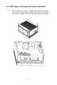
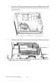
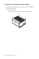
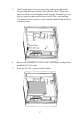
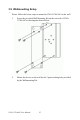
Table Of Contents
- Chapter 1 UNO-1170A/AE Overview
- Chapter 2 Hardware Functionality
- 2.1 UNO-1170A/AE Peripherals
- 2.2 COM1~COM2: RS-232 Interfaces
- 2.3 COM3: RS-232/422/485 Interfaces
- 2.4 IRQ and Address Setting
- 2.5 LAN: Ethernet Connector
- 2.6 Power Connector
- 2.7 LED Indicators
- 2.8 PS/2 Keyboard and Mouse Connector
- 2.9 Universal Serial Bus Connectors
- 2.10 VGA: VGA Display Connector
- 2.11 RESET: Reset Button
- 2.12 Audio
- 2.14 LED and Buzzer for System Diagnosis (Diag LED)
- 2.15 PCI/104+ Connectors (UNO-1170AE only)
- Chapter 3 Initial Setup
- Appendix A System Settings and Pin Assignments
- A.1 Interrupt Assignments
- A.2 Board Connectors and Jumpers
- A.3 RS-232 Serial Port (COM1~COM2)
- A.4 RS-232/422/485 Serial Port (COM3)
- A.5 Ethernet RJ-45 Connector (LAN1~LAN2)
- A.6 Power Screw Terminal (CN3)
- A.7 PS/2 Keyboard and Mouse Connector (CN8)
- A.8 USB Connector (CN4)
- A.9 VGA Display Connector (CN6)
- A.10 SATA Data Connector
- Appendix B Programming the Watchdog Timer
UNO-1170A/AE User Manual 24
2. Insert the USB keypro/dongle into the internal USB connector and
place the keypro bracket as shown in the picture. Then, screw the
keypro bracket.
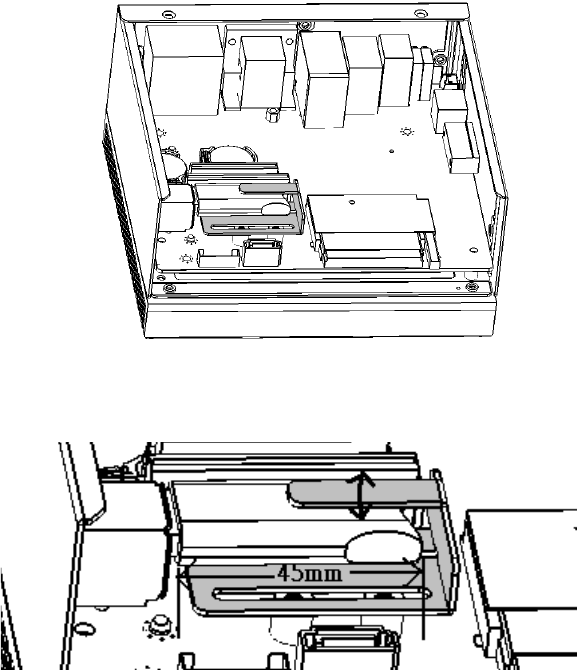
3. Manually adjust the bracket to perfectly fit the USB keypro/dongle.
(Note: Due to the extremely compact space in the chassis, the length for
USB keypro has to be limited to 45mm)