UNO-2174A/2178A Automation Computers with Intel® Atom™ Processors, 6 x USB, 8 x COM, 2 x Mini-PCIe User Manual
Copyright This document is copyrighted, © 2010. All rights are reserved. The original manufacturer reserves the right to make improvements to the products described in this manual at any time without notice. No part of this manual may be reproduced, copied, translated or transmitted in any form or by any means without the prior written permission of the original manufacturer. Information provided in this manual is intended to be accurate and reliable.
Product Warranty Advantech warrants to you, the original purchaser, that each of its products will be free from defects in materials and workmanship for one year from the date of purchase. This warranty does not apply to any products that have been repaired or altered by persons other than repair personnel authorized by Advantech, or which have been subject to misuse, abuse, accident or improper installation. Advantech assumes no liability under the terms of this warranty as a consequence of such events.
Declaration of Conformity CE This product has passed the CE test for environmental specifications when shielded cables are used for external wiring. We recommend the use of shielded cables. This kind of cable is available from Advantech. Please contact your local supplier for ordering information. FCC Class A Note: This equipment has been tested and found to comply with the limits for a Class A digital device, pursuant to part 15 of the FCC Rules.
1. 2. 3. 4. 5. 6. 7. 8. 9. 10. 11. 12. 13. 14. 15. 16. 17. 18. 19. 20. 21. 22. Safety Instructions Read these safety instructions carefully. Keep this User Manual for later reference. Disconnect this equipment from any AC outlet before cleaning. Use a damp cloth. Do not use liquid or spray detergents for cleaning. For plug-in equipment, the power outlet socket must be located near the equipment and must be easily accessible. Keep this equipment away from humidity.
TURER, DISCARD USED BATTERIES ACCORDING TO THE MANUFACTURER'S INSTRUCTIONS. 23. The sound pressure level at the operator's position according to IEC 704-1:1982 is no more than 70 dB (A). DISCLAIMER: This set of instructions is given according to IEC 704-1. Advantech disclaims all responsibility for the accuracy of any statements contained herein.
Contents Chapter 1 Overview ...........................................................2 1.1 1.2 1.3 1.4 Introduction ....................................................................... 2 Hardware Specifications ................................................... 3 Safety Precautions ............................................................. 5 Chassis Dimensions........................................................... 6 Figure 1.1:UNO-2174A Chassis Dimensions................. 6 Figure 1.
2.16 Chapter PCI Express Mini Card Socket........................................ 19 3 Initial Setup.....................................................22 3.1 3.2 Inserting a CompactFlash Card ....................................... 22 Chassis Grounding .......................................................... 22 3.3 3.4 3.5 3.6 Connecting Power ........................................................... 23 Installing a Hard Disk .....................................................
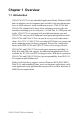
CHAPTER 1 2 Overview This chapter provides an overview of UNO-2174A/2178A’s specifications.
Chapter 1 Overview 1.1 Introduction UNO-2174A/2178A is an embedded Application Ready Platform (ARP) that can shorten your development time and offers rich networking interfaces to fulfill extensive needs in different projects. UNO-2174A and UNO-2178A include Intel’s latest Atom technology and provide rich interfaces including up to 4 serial ports, 2 x GbE Lan, 6 x USB ports and Audio.
1.2 Hardware Specifications General • Certifications Energy Star, CE, FCC class A, UL, CCC, IP40, BSMI, C-Tick • Dimensions (W x D x H)2174A: 255 x 152 x 50 mm (10' x 6.0' x 2.0") 2178A: 255 x 152 x 59 mm (10' x 6.0' x 2.3") • Enclosure Aluminum +SECC • Mounting Wallmount, DIN-rail, VESA • Industrial Grounding Isolation between chassis and power ground • Power Consumption UNO-2174A: 12W (Typical) UNO-2178A: 16W (Typical) • Power Requirements 9 ~ 36 VDC (Min. 36 W) • Weight 2.
I/O Interface • Serial Ports 2174A: 2 x RS-232/485 (COM1-2), 2 x RS-232/422/485 w/ 128kB FIFO (COM A-B) 2178A: 2 x RS-232/485 (COM1-2), 2 x RS-232/422/485 w/ 128kB FIFO (COMA-B), 4 x RS-232/485 from DB25 print port (COM3-6) • Serial Port Speed 50-115.2 kbps (COM 1-6 in RS-232/485 mode) 50-115.2 kbps (COM A/B in RS-232 mode) 50-921.6 kbps (COM A/B RS-422/485 model) • LAN 2 x 10/100/1000 Base-T RJ-45 ports (Built-in boot ROM in flash BIOS) Teaming function, Wake on LAN, Boot from LAN • Audio 5.
Expansion Board Reserved Functions • Battery Backup SRAM* 1MB • Mini-PCIe* 1 x Mini-PCIe • HDD* 1 x SATA II *Note: This function is reserved for projects 1.3 Safety Precautions The following sections tell how to make each connection. In most cases, you will simply need to connect a standard cable. Warning! Always disconnect the power cord from your chassis whenever you are working on it. Do not connect while the power is on. A sudden rush of power can damage sensitive electronic components.
9.64 159.41 1.4 Chassis Dimensions 227.80 49.30 254.80 149.64 159.41 Figure 1.1: UNO-2174A Chassis Dimensions 227.80 58.70 254.80 Figure 1.
1.5 Accessories Please refer below for the accessory list: • 3-pin connector for power wiring (Advantech P/N : 1652003206) • SATA signal cable (Advantech P/N : 1700006812) • SATA power cable (Advantech P/N : 1700004712) • 8 PCS jumper (Advantech P/N : 1653302122) • 4 COM port expansion cable (UNO-2178A only, P/N: 1700000146) • Keyboard/Mouse Y cable (Advantech P/N : 1700060202) • Driver DVD • Warranty card If anything is missing or damaged, contact your distributor or sales representative immediately.
UNO-2174A/2178A User Manual 8
CHAPTER 2 2 Hardware Functionality This chapter shows how to setup the UNO-2174A/2178A’s hardware functions, including connecting peripherals, setting switches and indicators.
Chapter 2 Hardware Functionality 2.1 Introduction The following figures show the connectors on UNO-2174A/2178A. The following sections give you information about each peripheral. Figure 2.1: Front Panel of UNO-2174A Figure 2.2: Front Panel of UNO-2178A Figure 2.3: Rear Panel of UNO-2174A Figure 2.
2.2 UNO-2174A/2178A Interface (COM1~COM6) UNO-2174A offers two standard RS-232/485 serial communication interface ports: COM1 and COM2. Note: UNO-2178A offers additional 4 RS-232/485 COM port COM3 ~ COM6 through expansion cable connected from DB25 pin.
2.3.1 16C550 UARTs with 128-byte standard Advantech UNO-2174A/2178A comes with OXuPCI952 UARTs containing 128 bytes FIFOs. These upgraded FIFOs greatly reduce CPU overhead and are an ideal choice for heavy multitasking environments. 2.3.2 RS-422/485 detection In RS-422/485 mode, UNO-2174A/2178A automatically detects signals to match RS-422 or RS-485 networks. (No jumper change required) 2.3.
2.4 Terminal Resistor Setup for RS-422/485 The onboard termination resistor (120 Ohm) for COM1-6, COM A, and COM B can be used for long distance transmission or device matching (Default Open). Each terminal resistor responds to different channels for RS-422/485. Usually, these resistors are needed for both ends of the communication wires and the value of the resistors should match the characteristic impedance of the wires used.
2.5 RS-232/422/485 Selection COM1 to COM2 support 9-wire RS-232 and RS-485 interfaces. COM3 to COM6 (UNO-2178A) support 4 wire RS-232 and RS-485 interfaces. COM A and COM B support 9-wire RS-232/422/485 interface. The system detects RS-422 or RS-485 automatically for COM A and COM B. To select between RS-232 or RS-485 for COM1 - COM6, adjust JCOM1 to JCOM6 accordingly. For COM A and COM B the corresponding jumpers for RS-232/422/485 selection are JCOM A and JCOM B. 2.5.
Figure 2.8: RS-485 Jumper Setting (COM3-6) 2.5.
2.5.3 RS-485 Auto Flow & RS-422 Master/Slave Mode You can set the “Auto Flow Control” mode of RS-485 or “Master/Slave” mode of RS-422 by using the SW4 DIP switch for COM A and COM B.. In RS-485, if the switch is set to “Auto”, the driver automatically senses the direction of the data flow and switches the direction of transmission. No handshaking is necessary. In RS-422, if DIP switch is set to “On,” the driver is always enabled, and always in high or low status. Table 2.
2.7 Power Connector The UNO-2174A/2178A comes with a Phoenix connector that carries 9~36 VDC external power input, and features reversed wiring protection. Therefore, it will not cause any damage to the system by reversed wiring of ground line and power line. Please refer to Appendix A.6 2.8 PS/2 Keyboard and Mouse Connector The UNO-2174A/2178A provides a PS/2 keyboard and mouse connector. A 6-pin mini-DIN connector is located on the rear panel.
2.12 RTC Battery Specification UNO-2174A/2178A has RTC Battery to ensure the setting in bios and system clock can be kept, even with power disconnected for a short time. • Type: BR2032 (Using CR2032 is NOT recommended) • Output Voltage: 3 VDC • Location: BH1, please refer to below figure Figure 2.9: RTC Battery Location 2.13 Power Button / Power Management Press the "PWR" button to power on or power off UNO-2174A/2178A (ATX type).
2.14 Reset Button Press the "Reset" button to activate the hardware reset function. 2.15 HD Audio UNO-2174A/2178A is equipped with ALC892-GR which is a High Definition Audio Codec. UNO-2174A/2178AF provides 3 phone jack connector for 5.1 channel output. Please configure the function through provided software utility. 2.16 PCI Express Mini Card Socket UNO-2174A/2178A supports two sockets for PCI Express mini cards. This interface is mainly target on the wireless application such as WLAN GPRS and 3G.
UNO-2174A/2178A User Manual 20
CHAPTER 3 2 Initial Setup This chapter introduces how to initialize the UNO-2174A/2178A.
Chapter 3 Initial Setup 3.1 Inserting a CompactFlash Card 1. Remove the power cord. 2. Unscrew the two screws of CF cover in the front panel. 3. Plug a CompactFlash card with your OS and application program into a CompactFlash card slot on board. 4. Screw back the CF cover to ensure IP40 protection. Note: The CompactFlash is allocated as "the Secondary IDE Master" by default. User can change it to "Primary IDE Master" by BIOS setting.
3.3 Connecting Power Connect the UNO-2174A/2178A to a 9~36 VDC power source. The power source can either be from a power adapter or an in-house power source. 3.4 Installing a Hard Disk The procedure for installing a hard disk into the UNO-2174A/2178A is below. Please follow these steps carefully. Please note the system is not compatible with +12V HDD. Please use an HDD with lower power input. 1. Remove the power cord. 2. Unscrew the six screws from the bottom panel. 3.
3.5 Installing a Wireless LAN Card and Antenna Please contact Advantech to prepare the following optional kit: Rear Panel for Antenna • The internal cable : 1700001854 (11cm) Wireless Module ( PCI Express mini card ) • One of the suggested module is 968EMW0021 which is a verified Wireless IEEE 802.11b/g/n module Antenna • Please select the necessary specification according to your application. • One of the suggested antenna is a verified 802.
4. Plug the Wireless module onto the PCI Express mini card socket (CN27 or CN31) 5. Connect the internal cable with the module. 6. Screw back the bottom panel. 7. Assemble the antenna on the SMA connector. 3.6 BIOS Setup Press "DEL" in the boot-up screen to enter the BIOS setup utility. Please follow the instruction on the screen to do the necessary settings. Please note that you can try to “Load Optimized Defaults” from the BIOS Setup manual if the UNO-2174A/2178A does not work properly.
UNO-2174A/2178A User Manual 26
Appendix A System Settings and Pin Assignments
Appendix A System Settings and Pin Assignments A.1 System I/O Address and Interrupt Assignment Table A.1: UNO-2174A/2178A Interrupt Assignments Interrupt No.
A.2 Board Connectors and Jumpers There are several connectors and jumpers on the UNO-2174A/2178A board. The following sections tell you how to configure the UNO-2174A/ 2178A hardware setting. Figure A-1 shows the locations of UNO-2174A/ 2178A’s connectors and jumpers. Figure A.
Table A.
A.3 RS-232/485 Standard Serial Port (COM1~COM2) Table A.
A.4 RS-232/485 Serial Port (COM3-COM6) This function is enabled through expansion cable (UNO-2178A only). Table A.
A.5 RS-232/422/485 Serial Port (COM A ~ COM B) Table A.5: RS-232/422/485 Serial Port Pin Assignments Pin RS-232 RS-422 RS-485 1 DCD TX- Data- 2 RxD TX+ Data+ 3 TxD RX+ NC 4 DTR RX- NC 5 GND GND GND 6 DSR NC NC 7 RTS NC NC 8 CTS NC NC 9 RI NC NC A.6 Power Connector (PWR) Table A.
A.7 PS/2 Keyboard and Mouse Connector 6 5 4 3 2 1 Table A.7: Keyboard and Mouse connector pin assignments Pin Signal Name 1 KB DATA 2 MS DATA 3 GND 4 VCC 5 KB Clock 6 MS Clock A.8 USB Connector Table A.
A.9 VGA Display Connector 5 1 10 6 15 11 Table A.
A.10 Clear CMOS (JP2) This jumper is used to erase CMOS data and reset system BIOS information. Follow the procedures below to clear the CMOS. 1. Turn off the system. 2. Close jumper JP2 (2-3) to clear CMOS . 3, Remove jumper JP2 (1-2) 3. Turn on the system. The CMOS is now cleared. 4. Turn on the system. The BIOS is reset to its default setting. Table A.10: JP2 Clear CMOS Configuration Function Clear CMOS Normal ( Default) A.