USB Wireless LAN Adapter User’s Manual Model # AWN-USB-54S 1
FCC Warning This equipment has been tested and found to comply with the limits for a Class B digital device, pursuant to part 15 of the FCC Rules. These limits are designed to provide reasonable protection against harmful interference in a residential installation. This equipment generates, uses, and can radiate radio frequency energy and, if not installed and used in accordance with the instructions, may cause harmful interference to radio communication.
Revision History Revision History V1.1 Second release All brand and product names mentioned in this manual are trademarks and/or registered trademarks of their respective holders.
Contents 1. 2. 3. Introduction.............................................................................................5 1.1 Features ........................................................................................5 1.2 LED Indicator................................................................................5 1.3 Package Contents ........................................................................5 Installation Procedure ..........................................................
1. Introduction This adapter is an IEEE 802.11g client device that delivers unrivaled wireless performance for your desktop PC or laptop PC. With this adapter, you can easily upgrade your computer wireless connectivity. Once connected, access your high-speed Internet connection while sharing photos, files, music, video, printers, and storage. Get a better Internet experience with a faster wireless connection so you can enjoy smoother digital phone calls, gaming, downloading, and video streaming.
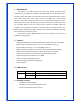
2. Installation Procedure Note: If you have installed the Wireless USB 2.0 Adapter driver & utility before, please uninstall the old version first. 2.1 Install Driver & Utility Note: The following installation was operated under Windows XP. (Procedures will be same for Windows 2000 / Windows ME / Windows 98SE) STEP1: Found New Hardware Wizard is displayed after the adapter is plugged. Please click Cancel to continue.
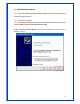
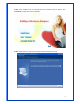
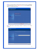
STEP2: Insert Installation CD into CD-ROM drive then windows below will appear. Click Install Driver to begin device driver installation. STEP3: Please wait for a while during the Setup Wizard is preparing the setup.
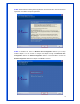
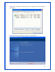
STEP4: Please read the following license agreement. Use the scroll bar to view the rest of this agreement. Click Yes to accept the agreement. STEP5: In Windows XP, there is a Windows Zero Configuration Tool for you to setup wireless adapter. You can choose to configure the adapter through the Microsoft Zero Configuration Tool or the Ralink Configuration Tool. It is recommended to choose the Ralink Configuration Tool for the adapter. Click Next to continue.
STEP6: If you need the adapter to operate with better performance, please choose Optimize for performance mode to enable the Tx Burst mode. Or you can choose Optimize for WiFi mode to run in standard wireless network. STEP7: Please wait for a while during the adapter is configuring your new software installation.
STEP8: When the adapter is installed properly, the configuration utility will be displayed automatically. STEP9: After the setup has finished the installing and click Finish button.
To check if the adapter is properly installed, you can right-click My Computer choose Properties click Device Manager. The Configuration Utility appears as an icon on the system tray of Windows while the adapter is running. You can open the utility by double-click on the icon. Right-click the icon, there are some items for you to operate the configuration utility, Launch Config Utilities Select this option to open the Configuration Utility tool.
2.2 Install Driver for Vista Step 1: Once USB Wireless LAN Card is plugged into the Computer, you will see the Found New Hardware windows is shown as below. Click Cancel to close this window. Step 2: Insert the Install CD-Rom and Setup program will display. Click Install Driver to start device driver installation.
Step 3: Please wait for a while during the USB Wireless LAN Card is configuring your new software installation. Step 4: After setup has finished installing, click Finish to exit the wizard.
To check if the adapter is properly installed, you can right-click My Computer choose Properties click Device Manager.
3. Wireless Network Configuration Utility The Configuration Utility is a powerful application that helps you to configure the Wireless USB 2.0 adapter and monitor the link status and statistics during the communication process. When the USB adapter is installed, the configuration utility will be displayed automatically. This adapter will auto connect to wireless device which has better signal strength and no wireless security setting.
STEP3: Uncheck “Use Windows to configure my wireless network settings” to enable the utility for the adapter and then click OK to continue. Note: If “Wireless Zero Configuration” is enabled, you can only configure the advance setting or check the link status and statistics from the configuration utility of the adapter. 3.1 Profile In the “Profile”, you can view and manage the current using Available Point(s). You can Add, Delete, Edit, or Activate the current Available Point(s).
3.2 Link Status In this section, you can immediately monitor the current connected link status, such as Link Speed, Throughput, Link Quality, Signal Strength, Noise Level …etc.
Status: Display the SSID and MAC ID of the network that the adapter is connecting to. Extra Info: Display the link status. Channel: Display the number of the radio channel and the frequency used for the networking. Link Speed (Mbps): Display the transmission and reception rate of the network. The maximum transmission rate is 54Mbps. Throughput (Kbits/sec): Display data transmitted and received throughput in unit of K bits per sec. Link Quality: This bar indicates the quality of the link.
make connection. If the intended network has encryption other than “ Not Use ”, RaConfig will bring up the security page and let use input the appropriate information to make the connection Available Network: This list shows all available wireless networks within range of your adapter. It also displays the information of the networks including the SSID, BSSID, Signal Strength, Channel, Encryption, Authentication, and Network Type.
Profile Name: Define a recognizable profile name for you to identify the different network. SSID: The SSID (up to 32 printable ASCII characters) is the unique name identified in a WLAN. The ID prevents the unintentional merging of two co-located WLANs. You may specify a SSID for the adapter and then only the device with the same SSID can interconnect to the adapter.
stations. If there are only 802.11b wireless stations in the network, you can set the card to this mode. 802.11 B/G mix – If you have a mix of 802.11b and 802.11g wireless stations in your network, it is recommended to setting the card to this mode. This mode is also the default setting. 802.11 G only –This card can be compatible with both 802.11g and 802.11b wireless stations. If there are only 802.11g wireless stations in the network, you can set the card to this mode.
3.3.2 Authentication and Security Authentication Type: This setting has to be consistent with the wireless networks that the adapter intends to connect. Open: No authentication is needed among the wireless devices. Shared: Only Wireless device using a shared key (WEP Key identified) is allowed to connecting each other. Setup the same key as the wireless device that the adapter intends to connect. LEAP: LEAP is a pre-EAP, Cisco-proprietary protocol, with many of the features of EAP protocols.
WPA2 – Like WPA, WPA2 supports IEEE 802.1x/EAP authentication or PSK technology. It also includes a new advanced encryption mechanism using the Advanced Encryption Standard (AES). AES is required to the corporate user or government users. The different between WPA and WPA2 is that WPA2 provides data encryption via the AES. In contrast, WPA uses Temporal Key Integrity Protocol (TKIP). WPA2-PSK – WPA2-PSK is also for home and small business.
Fill the text box by following the rule below: 64-bit – Input 10-digit Hex values (in the “A-F”, “a-f, and “0-9” range) or 5-digit ASCII characters (including “a-z” and “0-9”) as the encryption keys. For example: “0123456aef” or “test1” 128-bit – Input 26-digit Hex values (in the “A-F”, “a-f, and “0-9” range) or 13-digit ASCII characters (including “a-z” and “0-9”) as the encryption keys. For example: “01234567890123456789abcdef” or “administrator” 3.3.3 802.1x Setting-Certification The IEEE 802.
Authentication Type: The EAP authentication protocols this adapter has supported are included as follows. This setting has to be consistent with the wireless APs or Routers that the adapter intends to connect. PEAP: Protect Extensible Authentication Protocol. PEAP transport securely authentication data by using tunneling between PEAP clients and an authentication server.
Identity: Enter the name as the identity for the server. Password: Enter the password as the identity for the server. Use Client Certificate: A client certificate is required for TLS, and is optional for TTLS and PEAP. This forces a client certificate to be selected from the appropriate Windows Certificate Store and made available to the RADIUS server for certification.
Allow Intermediate Certificates: A server designates an issuer as a trusted root authority by placing the issuer’s self-signed certificate, which contains the issuer’s public key, into the trusted root certification authority certificate store of the host computer. Intermediate or subordinate certification authorities are trusted only if they have a valid certification path from a trusted root certification authority. Server Name: Enter the authentication server name.
or more reties. 4. Frames Fail To Receive ACK After All Retries: Frames failed transmit after hitting retry limit. 5. RTS Frames Successfully Receive CTS: Successfully receive CTS after sending RTS frame. 6. RTS Frames Fail To Receive CTS: Failed to receive CTS after sending RTS. Receive Statistics: 1. Frames Received Successfully: Frames received successfully. 2. Frames Received With CRC Error: Frames received with CRC error. 3. Frames Dropped Due To Out-of-Resource: Frames dropped due to resource issue.
802.11 B only – This adapter can be compatible with both 802.11g and 802.11b wireless stations. If there are only 802.11b wireless stations in the network, you can set the adapter to this mode. 802.11 G only –This adapter can be compatible with both 802.11g and 802.11b wireless stations. If there are only 802.11g wireless stations in the network, you can set the adapter to this mode. Ad Hoc Wireless mode: There are four types. 802.11B only, 802.11 B/G mixed 802.11A only, and 802.
applied to the multimedia application or a voice call. The adapter will fast roaming to the near network when the receive sensitivity (signal strength) is lower to the value you have set up. Turn Off RF Button: If you want to turn off the radio of the adapter temporarily, click this button. To turn on the radio, click this button again. Radio On: Indicate to turn on radio. Radio Off: Indicate to turn off radio. CCX 2.0: CCX 2.
3.6 QoS The QoS Page of RaConfig. It involves “WMM Enable”, “WMM – Power Save Enable” and DLS setup. WMM Enable: Enable Wi-Fi Multi-Media. WMM – Power Save Enable: Enable WMM Power Save. Direct Link Setup Enable: Enable DLS (Direct Link Setup). 3.6.1 Configure to enable Wi-Fi Multi-Media If you want to use “WMM – Power Save” or “Direct Link”, you must enable WMM. The setting method of enabling WMM indicates as follows: Step1: Click “WMM Enable” Step2: Click “Apply”.
Step3: Change to “Site Survey Page”. And add an AP that supports WMM features to a Profile. The result will look like the below figure in Profile page.
3.6.2 Enable WMM – Power Save Step1: Click “WMM – Power Save Enable”. And Click “Setting…” button. Step2: After clicking “Setting…” button, show “Power Save Setting” dialog. Please select which ACs you want to enable. Then click “Apply” button. The setting of enabling WMM – Power Save is successfully.
3.6.3 Enable DLS (Direct Link Setup) Step1: Click “Direct Link Setup Enable”. And Click “Apply” button Step2: Change to “Site Survey Page”. And add an AP that supports DLS features to a Profile. The result will look like the below figure in Profile page.
The Setting of DLS indicates as follow: 1. Fill in the blanks of Direct Link with MAC Address of STA. The STA must conform to two conditions as follow: Step1: Connect with the same AP that support DLS features. Step2: Have to enable DLS. 2. Timeout Value represents that it disconnect automatically after some seconds. The value is integer. The integer must be between 0~65535. It represents that it always connects if the value is zero.
3. Click “Apply” button. The result will look like the below figure. Describe “DLS Status” as follow: 1. As the up figure, after configuring DLS successfully, show MAC address of the opposite side and Timeout Value of setting in “DLS Status”. In “DLS Status” of the opposite side, it shows MAC address of myself and Timeout Value of setting. 2.
Step2: Double click. And the result will look like the below figure. 3. Disconnect Direct Link Setup as follow: Step1: Select a direct link STA.
Step2: Click “Tear Down” button. The result will look like the below figure. 3.7 About About page display the wireless card and driver version information.
In the “About”, you can click the hyperlink to connect the website for the information of the wireless chipset vendor and review basic information about the Utility such as the RaConfig Version, Driver Version, EEPROM Version, IP Address, Sub Mask, and Default Gateway.
4. Troubleshooting This chapter provides solutions to problems usually encountered during the installation and operation of the adapter. 1. Symptom: The LED is Off. Possible Remedy: Make sure the Wireless adapter is inserted properly. Otherwise, please contact your vendor. 2. Symptom: The LED is always on not blinking. Possible Remedy: Make sure that you have installed the driver from the attached CD. 3. Symptom: The LED is blinking but the Wireless adapter icon does not appear in your icon tray.
Possible Remedy: Move the antennas of the access point or wireless router into an L shape (one vertically, and one horizontally). Click on the Refresh button on the Site Survey screen. If the computer still does not see the Access Point, and then try to move your Access Point closer to the computer. Then click on the Refresh button again. If the computer still does not see the Access Point, move all things that may cause interference with the wireless signal. 8.
10. What does IEEE 802.11 feature support? The product supports the following IEEE 802.11 functions: -- CSMA/CA Plus Acknowledge Protocol -- Multi-Channel Roaming -- Automatic Rate Selection -- RTS/CTS Feature -- Fragmentation -- Power Management 11. What is Ad-Hoc? An Ad-Hoc integrated wireless LAN is a group of computers, each has a Wireless LAN adapter, Connected as an independent wireless LAN. Ad-Hoc wireless LAN is applicable at a departmental scale for a branch or SOHO ope ration. 12.
software than previous encryption standards. It is also included in IEEE 802.11i standard. Compare with AES, TKIP is a temporary protocol for replacing WEP security until manufacturers implement AES at the hardware level. 17. Would the information be intercepted while transmitting on air? WLAN features two-fold protection in security. On the hardware side, as with Direct Sequence Spread Spectrum technology, it has the inherent security feature of scrambling.