Instruction Manual 2 Genesis® G2 model H y d ro - P n e u m a t i c P o w e r To o l
Contents Safety Rules 4 Specification Tool Specification Tool Dimensions 5 5 Intent of Use Range of Fasteners Part Numbering 6 6 Putting into Service Air Supply Operating Procedure Adjusting the Vacuum Extraction 7 7 7 Nose Assemblies Fitting and Servicing Instructions Selection of Nose Tips 8 9&10 Accessories Stem Deflector Extension Side Ejector Swivel Heads Preparing the Base Tool Swivel Head Fitting Instructions Swivel Head Servicing Instructions 11 11 11 12 13 14 15 Servicing the Tool Daily
Safety Rules This instruction manual must be read with particular attention to the following safety rules, by any person installing, operating, or servicing this tool. 1 Do not use outside the design intent. 2 Do not use equipment with this tool/machine other than that recommended and supplied by Textron Fastening Systems.
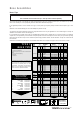
Specifications To o l S p e c i f i c a t i o n Air Pressure Minimum - Maximum 5-7 bar Free Air Volume Required @ 5.5 bar 2.1 litres Stroke Minimum 17 mm Pull Force @ 5.5 bar 9.34 kN Cycle Time Approximately 0.9 seconds Noise Level 75 dB(A) Weight Without nose equipment 1.35 kg Vibration Less than 2.
Intent of Use Range of Fasteners G2 is a hydro-pneumatic tool designed to place Avdel® breakstem fasteners at high speed making it ideal for batch or flow-line assembly in a wide variety of applications throughout all industries. It can place all fasteners listed opposite. The tool features an adjustable vacuum system for fastener retention and trouble free collection of the spent stems regardless of tool orientation. See the ‘Operating Procedure’ on page 7 for adjustment instructions.
Putting into Service Air Supply All tools are operated with compressed air at an optimum pressure of 5.5 bar. We recommend the use of pressure regulators and filtering systems on the main air supply. These should be fitted within 3 metres of the tool (see diagram below) to ensure maximum tool life and minimum tool maintenance. Air supply hoses should have a minimum working effective pressure rating of 150% of the maximum pressure produced in the system or 10 bar, whichever is the highest.
Nose Assemblies Fitting Instructions I M P O R TA N T The air supply must be disconnected when fitting or removing nose assemblies. Item numbers in bold refer to nose assembly components in all 3 nose tip tables. • Lightly coat jaws 4 with Moly lithium grease*. • Drop jaws 4 into jaw housing 3. • Insert jaw spreader 5 into jaw housing 3. • Locate buffer 6 on jaw spreader 5. • Locate spring 7 onto jaw spreader 5. • Fit locking ring 8 onto the jaw spreader housing of the tool.
Nose Assemblies Nose Tips I M P O R TA N T Nose assemblies do NOT include nose tips. Nose tips must be ordered separately. A tool (except part number 71210-00039) must always be fitted with the correct nose assembly and nose tip for your fastener but if you wish to order a nose assembly or a nose tip separately, refer to the ‘NOSE TIPS’ tables below and page 10.
Nose Assemblies Nose Tips FASTENER MATERIAL Ø1 1/8 3.2 Aluminium Alloy 1/8 3.2 Steel 5 / 32 4.0 Aluminium Alloy 5 / 32 4.0 Steel 3 / 16 4.8 Aluminium Alloy 3 / 16 4.8 Steel 5 ® / 32 BULBEX 4.0 Aluminium Alloy 3 / 16 4.8 Aluminium Alloy – T-LOK ® 4.3 Steel 3 / 16 4.8 Steel 1/8 STAVEX ® 3.2 Steel 5 / 32 4.0 Steel 3 / 16 4.8 Steel 1/8 3.2 Stainless Steel 5 / 32 4.0 Stainless Steel 3 / 16 4.8 Stainless Steel AVIBULB ® 1/8 3.2 Steel 5 / 32 4.0 Steel – E.T.R 5.
Accessories Stem Deflector The stem deflector is a very simple alternative to the standard stem collector and allows access in restricted areas. To replace the stem collector with the stem deflector proceed as follows: • • • • • Unscrew retaining nut 21 by inserting a 3 millimetre diameter rod into one of the holes. Remove retaining nut 21 and the stem collector assembly, items 15, 16, 17, 18, 19, and 20. Screw the adaptor nut onto end cap 22.
Accessories Swivel Heads Instead of a nose assembly, a swivel head can be fitted to a base tool. It allows 360° rotation of the tool about the nose tip and allows access into many applications otherwise too restrictive. There are two types of swivel heads: the straight swivel head with the nose tip slightly offset from the centre line of the tool head and the right-angle swivel head with the nose tip on a perpendicular axis to the head of the tool.
Accessories P r e p a r i n g t h e B a s e To o l • • • • • • • • Disconnect the air supply. Remove any nose assembly items. Remove retaining nut 22 and all elements of the stem collector (items 18, 19, 20, 21, 45, 63, 64). Note that ‘O’ ring 17 remains. Replace the above with a safety cap as shown in drawing opposite. Unscrew jaw spreader housing 1 and remove with ‘O’ ring 2, locknut 3, ‘O’ rings 68 and 67, and seal housing 5.
Accessories The fitting and servicing procedures for both types of head are almost identical. Differences are clearly indicated. I M P O R TA N T PRIOR to fitting a swivel head, the base tool must be adapted. See Preparing the base tool opposite. The air supply must be disconnected when fitting or removing swivel heads. Swivel Head Fitting Instructions The following procedure will allow you to assemble and fit either of the swivel heads to the tool.
Accessories Swivel Head Servicing Instructions Swivel heads should be serviced at weekly intervals. • Remove the complete head using the reverse procedure to the ‘Fitting instructions’ omitting step ‘L’. 17 • If guard 1 is at all damaged it must be replaced by a new one. • Any worn or damaged parts should be replaced. • Pay particular attention to jaw carrier items in the upper illustration opposite as follows: Check wear on jaws 17. Check that jaw spreader tube 18 is not distorted.
S e r v i c i n g t h e To o l I M P O R TA N T Read Safety Instructions on page 4. The employer is responsible for ensuring that tool maintenance instructions are given to the appropriate personnel. The operator should not be involved in maintenance or repair of the tool unless properly trained. The tool shall be examined regularly for damage and malfunction.
S e r v i c i n g t h e To o l Molykote 55m Grease Safety Data First Aid SKIN: Flush with water. Wipe off. INGESTION: No first aid should be needed. EYES: Flush with water. Fire FLASH POINT: Above 101.1°C. (closed cup) Explosive Properties: No Suitable Extinguishing Media: Carbon Dioxide Foam, Dry Powder or fine water spray. Water can be used to cool fire exposed containers. Environment Do not allow large quantities to enter drains or surface waters.
S e r v i c i n g t h e To o l Service kit For an easy complete service, Textron Fastening Systems offers the complete service kit below. SERVICE KIT : 71210-99990 PART Nº 07900-00667 07900-00692 07900-00670 07900-00672 07900-00706 07900-00684 07900-00685 07900-00351 07900-00469 07900-00158 18 DESCRIPTION PISTON SLEEVE TRIGGER VALVE EXTRACTOR BULLET 'T' SPANNER 'T' SPANNER SPIGOT GUIDE TUBE INSERTION ROD 3 MM ALLEN KEY 2.
S e r v i c i n g t h e To o l Annually (or every 500,000 cycles whichever is the soonest) Annually or every 500,000 cycles the tool should be completely dismantled and new components should be used where worn, damaged or recommended. All ‘O’ rings and seals should be renewed and lubricated with Molykote 55m grease for pneumatic sealing or Molykote 111 for hydraulic sealing. I M P O R TA N T Read Safety Instructions on page 4.
S e r v i c i n g t h e To o l Pneumatic Piston Assembly • Remove ‘ON/OFF’ valve assembly 55. • Clamp the body of the inverted tool across the air inlet bosses in a vice fitted with soft jaws. • Using the peg spanner* unscrew base cover 36 and pull out cylinder liner 41. • Remove pneumatic piston assembly 38 from body 34 together with ‘O’ ring 35, lip seal 37 and guide ring 31. • Screw the seal extractor* into seal assembly 30 and pull it out of the intensifier tube of head assembly 4.
Notes 21
2 3 4 71 5 6 7 8 9 10 11 65 12 16 13 14 15 53 52 45 17 54 18 19 66 49-51 47 46 68 67 69 48 50 66 55 B B 44 43 26 42 27 25 24 23 22 63 21 28 20 57 27 29 30 31 60 61 32 41 33 40 34 39 38 37 B-B 35 36 70 66 58 57 A-A 64 A A 59 56 G e n e r a l A s s e m b l y o f B a s e To o l 7 1 2 1 0 - 0 2 0 0 0 22 1
PART Nº DESCRIPTION 01 02 03 04 05 06 71210-02101 07003-00277 71210-02103 71210-03320 71210-02104 07003-00333 JAW SPREADER HOUSING 'O' RING LOCKNUT HEAD ASSEMBLY SEAL HOUSING LIP SEAL 07 08 09 10 11 71210-02121 07003-00273 07001-00405 07003-00194 07003-00341 HEAD PISTON LIP SEAL SCREW SEAL LIP SEAL 12 13 14 15 16 07003-00275 71210-02007 07003-00278 71210-02029 71210-02022 LIP SEAL STEM COLLECTOR ADAPTOR 'O' RING SEAL SUSPENSION RING 17 18 19 07003-00067 07640-00239 71210-02051 'O' RING STEM COL
Priming Priming is ALWAYS necessary after the tool has been dismantled and prior to operating. It may also be necessary to restore the full stroke after considerable use, when the stroke may be reduced and fasteners are not fully placed by one operation of the trigger. Oil Details The recommended oil for priming is Hyspin VG32 available in 0.5l (part number 07992-00002) or one gallon containers (part number 07992-00006). Please see safety data below.
Priming P r i m i n g P ro c e d u r e I M P O R TA N T DISCONNECT THE TOOL FROM THE AIR SUPPLY OR SWITCH OFF AT VALVE 55. REMOVE NOSE ASSEMBLY OR SWIVEL HEAD COMPONENTS. All operations should be carried out on a clean bench, with clean hands in a clean area. Ensure that the new oil is perfectly clean and free from air bubbles. Care MUST be taken at all times, to ensure that no foreign matter enters the tool, or serious damage may result. • Remove bleed screw 9 and seal 10.
Fault Diagnosis M PpTtO SSyYm oM m P oP sO sS iSbI Bl eL ECCaAuUsSeE M EeDdYy RReEm P aPA g GeE RReEfF More than one Air leak Tighten joints or replace components operation of the Insufficient air pressure Adjust air pressure to within specification 5 trigger needed to Lack of lubrication Lubricate tool at air inlet point 7 place fastener Worn or broken jaws Fit new jaws 8-10* Low oil level or air in oil Prime tool 24-25 Build up of dirt inside the nose assembly Service nose assembly
Declaration of Conformity We, Textron Fastening Systems Limited, Mundells, Welwyn Garden City, Herts, AL7 1EZ declare under our sole responsibility that the product: Model G2 Serial No. ................................................
SPAIN Textron Verbindungstechnik GmbH Textron Sistemas de Fijación S.A. 891 Wellington Road Klusriede 24 c/ Puerto de la Morcuera, s/n Rowville D - 30851 Langenhagen Poligono Industrial Prado Overa Victoria 3178 Tel: Autovia Madrid Toledo Km 7.8 Tel: Fax: +49 511 7288 133 Es - 28916 Leganes (Madrid) Email: info@avdel.de Tel: +613 9764 3877 Fax: +613 9755 7352 +49 511 7288 0 Email: custserv@textronfast.com.au +349 134 16767 Fax: +349 134 16740 ITALY Email: textronespana@tfsspain.