
Instruction manual


7
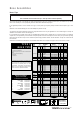
All tools are operated with compressed air at an optimum pressure of 5.5 bar. We recommend the use of pressure regulators and filtering
systems on the main air supply. These should be fitted within 3 metres of the tool (see diagram below) to ensure maximum tool life and
minimum tool maintenance.
Air supply hoses should have a minimum working effective pressure rating of 150% of the maximum pressure produced in the system or
10 bar, whichever is the highest. Air hoses should be oil resistant, have an abrasion resistant exterior and should be armoured where
operating conditions may result in hoses being damaged. All air hoses MUST have a minimum bore diameter of 6.4 millimetres or
1
/4 inch.
Read servicing daily details page 16.
8
6
4
2
0
1
0
1
2
14
1
6
TAKE OFF POINT
FROM
MAIN SUPPLY
STOP COCK
(USED DURING MAINTENANCE
OF FILTER/REGULATOR OR LUBRICATION UNITS)
MAIN SUPPLY
DRAIN POINT
PRESSURE REGULATOR
AND FILTER (DRAIN DAILY)
3 METRES MAXIMUM
2
• Ensure that either the correct nose assembly or swivel head suitable for the fastener is fitted (see pages 8-10 and 12-15).
• Connect the tool to the air supply.
• Insert the fastener stem into the nose of the tool. If using a nose assembly, the fastener should remain held in by the vacuum
system. If not, adjust the vacuum extraction rotary valve 60.
• If using a swivel head, the vacuum extraction is disabled but the jaws themselves will grip the fastener.
• Bring the tool with the fastener to the application so that the protruding fastener enters squarely the hole of the application.
• Fully actuate the trigger. The tool cycle will broach the fastener and with standard nose assemblies the broken stem will be
projected to the rear of the tool .
• Using a screwdriver, turn rotary valve 60 until the air flow at the rear of the tool ceases.
• With the nose of the tool pointing downwards, insert a fastener into the nose and hold it into position.
• Turn the rotary valve either way until there is sufficient suction to retain the fastener.
Item numbers in bold refer to the general assembly drawing and parts list on pages 22-23.
Putting into Service
Air Supply
Operating Procedure
Adjusting the Vacuum Extraction