R ADV285 S / ADV285 P DUAL 8.
Important Notice An LCD panel and / or video monitor may be installed in a motor vehicle and visible to the driver if the LCD panel or video monitor is used for vehicle information, system control, rear or side observation or navigation. If the LCD panel or video monitor is used for television reception, video or DVD play, the LCD panel or video monitor must be installed so that these features will only function when the vehicle is in “park” or when the vehicle’s parking brake is applied.
MATERIALS INCLUDED IN THIS PACKAGE: 1) 2) 3) 4) 5) 6) 7) 8) ADV285S/P TV / Video Monitor with DVD – (1 pc) 12 Pin Power / Signal harness (P/N 112-3483) – (1 pc) 2 Pin Power Wire Harness with choke (P/N 112B3143) – (1 pc) Hardware Package #4 x 5/16" Self Tapping Screws – (9 pcs) #8 x 3/8" Self Drilling Screws – (6 pcs) M5 x10mm Screws – (6 pcs) M5 Flat Washer – (6 pcs) Remote Control (P/N 136-4120) – (1 pc) Trim Ring – (1 pc) Game Controller (P/N 136-4212) (1 pc) Mounting Bracket (P/N 108-3895) – (1 pc) O
GENERAL INSTALLATION APPROACH: 1) Decide upon system configuration and options that will be installed (i.e.: what components, VCP, Video Game, external amp, wireless headphones, VCP, etc.). 2) Review all manuals to become familiar with electrical requirements and hook ups. 3) Decide upon mounting locations of all components and method of mounting.
VEHICLE PREPARATION: 1) Locate an accessory power source (+12v when key is in the ACC. and run positions, and 0v when key is off), and also a good ground generally, these wires can be found at the ignition switch or fuse-box. 2) The mounting method and location will vary from vehicle to vehicle, so this manual will only focus on the installation of the ADV285 and related console accessories. 3) Generally, the best location for the video monitor is where the vehicle's factory dome light is installed.
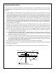
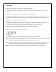
TRIM RING INSTALLATION: This page only covers special installation considerations for the trim ring installation. If the video monitor is to be installed in a vehicle with the trim ring, it may need to be trimmed to fit the contour of the vehicle headliner. 1) In this installation, the video monitor is mounted directly to the overhead cross-member in the roof using the mounting screw bosses. These screw bosses should contact the cross-member directly (i.e.
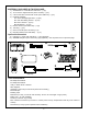
MOUNTING THE TRIM RING Roof Roof Support Headliner Mounting Bracket Self-drilling Screws Trim Ring Video Unit Washer M5 x10mm Screw 5
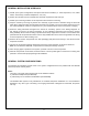
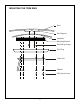
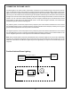
ADV285 Auxillary Video Display TV ANTENNA Line Out-R (Red) Line Out-L (White) Line Out-V (Yellow) Power Harness Item #3 (Optional) Dome Light Power source To TV Antenna In Power Harness Item #3 *** Optional PODTVT (See TV Tuner Note on next page) DIN 1 (AV1) PODTVT UNIT (BACK VIEW) DIN 2 * Antenna for Wireless FM Mod.
ADV285 1) Make the connections to the vehicle for the 12 pin wiring harness. 2) Connect power harness to vehicle’s electrical system by tapping into an accessory hot line and a good ground. 3) Connect the 12 pin harness to the mating connector on the Video Monitor. 4) If an auxiliary video input is used (VCP, DVD, etc) insert the Circular Mini-Din Connector of the source component harness through the wire tie loop on the main PCB and into the Mini-Din Connector on the main PCB.
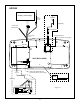
CONNECTING THE DOME LIGHTS The dome lights in the video monitor require three connections to the vehicle's wiring. There are two common types of dome light circuits used, positive or negative switched. Positive systems supply voltage to the interior lights to turn them on, negative switched systems apply ground to illuminate the bulbs. To determine which system you have you must locate the wires at the dome light.
Negative Switched Dome Lighting To 12 pin connector Red / black - Lamp on Black / red - Lamp common Purple / brown - Lamp Auto To constant To constant Factory Door ajar switch or Body Control computer Troubleshooting: SYMPTOM: REMEDY: No power at Video Monitor Verify +12 VDC on Red wire at 2 pin Power Harness behind video monitor.
8-7545A © 2005 ADVENT, 150 Marcus Blvd.