
Specifications

2
© 2012 Emerson Climate Technologies, Inc.
Printed in the U.S.A.
AE8-1368 R2
6.26 Control Module Failure Lockout
6.27 Sensor Module Failure
6.28 High Discharge Pressure Trip
6.29 Discharge Temperature Lockout
6.30 Current Overload Trip
6.31 Rapid Compressor Cycling with Constant
Demand
6.32 Discharge Temperature Probe Fault Trip
6.33 Comp Low Voltage Trip/Lockout
7.0 Service Instructions
7.1 Control Module Replacement
7.2 Sensor Module Replacement
7.3 Installation Torque Values
7.4 Demand Cooling Service Procedures
7.5 Temperature Probe Inspection
7.6 Coil Inspection and Replacement
7.7 Injection Valve Replacement
8.0 Compressor Changeout Instructions
9.0 Removal Of 2D / 3D
10.0 Installation Of 2D / 3D
11.0 Removal Of 4D
12.0 Installation Of 4D
13.0 Removal Of 6D
14.0 Installation Of 6D
Appendix
A. Terminal Box Diagram
B. Harness Wiring Diagram
C. Transformer Selection and Contactor Control
D. Dielectric Test (Hi-Pot)
E. Compressor Drawings
F. Technical Support Information
G. Service Parts List
1.0 Overview of the Copeland Discus Compressor
with CoreSense Diagnostics v2.11
CoreSense Diagnostics v2.11 is now available on 2D,
3D, 4D and 6D compressors and integrates a number
of important sensing and compressor protection
functions. This product provides for on/off control of the
compressor, capacity modulation (both conventional
blocked suction and with Copeland Discus Digital
™
capacity modulation) and for communication of the
compressor status to the rack controller through
a network using MODBUS for Intelligent Store
communication protocol. Protection against low oil
pressure, excessive discharge temperature, high
discharge pressure and low suction pressure is
standard on every Copeland Discus compressor
with CoreSense Diagnostics. A 2-line liquid crystal
display on the front of the compressor indicates the
operational status of the compressor with a choice
of 5 languages. An LED on the compressor control
module indicates at a glance whether or not there are
any compressor faults.
The “2.11 version” of this product provides the same
basic protection and feature package as the previous
“1.0” product, but with enhancements such as additional
motor protection, accessory proofi ng and modulation
control and demand cooling control.
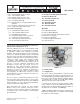
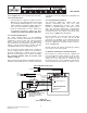
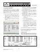
Note: Throughout this manual the term “Control
Module” refers to the electronic control box on the
front of the compressor which contains the display and
reset buttons. The “Sensor Module” is located inside
the terminal box.
Figure 1.1
1.1 Functionality
1.1.1 Diagnostics
The status of the Copeland Discus compressor with
CoreSense Diagnostics may be viewed at any time on
the LCD display by pushing the Display button on the
front of the control module. Normal conditions will be
accompanied by a steady green LED (light emitting
diode) on the front of the control module.
If a fault occurs that doesn’t interfere with the ability
of the compressor to run, the LED will transition to a
fl ashing green. The display will provide a description of
the fault. This is referred to as a warning.
A trip or lockout condition will result in a fl ashing red
LED. This is an indication of a condition that is keeping
the compressor from running.