
Specifications

4
© 2012 Emerson Climate Technologies, Inc.
Printed in the U.S.A.
AE8-1368 R2
1.2.2 Remote Reset
The oil pressure lockout may be reset through the E2
or remotely through Site Manager if the reset option is
enabled.
The service contractor and end user policies need
to be considered when deciding whether to enable
or disable the oil pressure remote reset feature. The
default condition is to “disable” this feature.
Refer to Section 4, Figure 4.15 for enabling or
disabling this remote reset.
1.2.3 Failsafe Operation
The FAILSAFE mode may be confi gured at any time
by setting the #10 dipswitch to the “on” or “off” position
as desired. The failsafe condition is acted upon by the
compressor in the event that communication is lost
for 5 or more minutes. Upon the re-establishment of
communication to the rack controller the run command
from the rack controller overrides the failsafe command.
The failsafe switch position may be changed at anytime.
However, the module must be reset before the control
module recognizes a change in the switch position.
When the compressor is running in the failsafe “on”
position, all of the compressor protection features are
enabled with the exception of welded contactor.
There are different philosophies regarding the failsafe
settings. One suggestion is to observe the typical
“percent of full load capacity” required to satisfy
demand (this is perhaps seasonal). Setting the
switches to provide this capacity (with perhaps a little
reserve) is one approach.
As with all dipswitch positions, a legend may be found
inside the lower cover of the control module that
explains the switch positions.
1.2.4 Welded Contactor Protection
Voltage is sensed at the motor terminals of the
Copeland Discus compressor with CoreSense
Diagnostics. If voltage is present after the contactor
has been signaled to “open”, the module will send a
welded contactor alarm to the E2. The E2 then issues
a run command to the module to load the contactor,
bringing all three legs of the power supply to the
compressor back on line. This prevents a single-phase
motor burn. The compressor will run continuously until
the unit is manually shut down or the alarm is cleared
in the E2. Safety devices (pressure switches and motor
protection) will attempt to override this feature.
This is not to be confused with single-phase protection
at start-up or while running. In that case, the contactor
will be instructed to “open”, shutting down the
compressor.
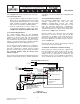
1.2.5 Crank Case Heater (CCH) Control
The sensor module contains an on-board CCH control
relay. An auxiliary contactor is no longer required to
turn the heater on when the compressor turns off.
The appropriate voltage supply to the CCH power input
terminals (115 V / 230 V) is required.
1.2.6 Start-up Delay Feature
To reduce the sudden in-rush of power associated
with multiple compressors starting at one time,
compressor start-ups are staggered slightly at the end
of the anti-short cycle delay. The delay is equal to 100
milliseconds x node number. Therefore node number
4 will start 0.3 seconds after node number 1. Refer to
the status code table to see which events trigger an
anti-short cycle delay.
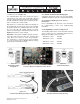
1.2.7 “Jog” Feature
The reset button on the front of the control module
may be used as an emergency shutdown, such as
for clearing liquid during a start-up. After the module
re-boots (approximately 30 seconds) the compressor
will run again. The reset button may be pushed as
necessary to stop the compressor.
1.2.8 Dipswitch Settings
Dipswitch selection for the address, baud rate, parity,
operating and failsafe mode selection simplify service
and start-up procedures. At initial power-up or after
pushing the Reset button, the following information will
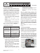
be displayed on the LCD:
Control Module Firmware Version
Sensor Module Firmware Version
Node Address
Baud Rate (9600 or 19200)
Parity (Parity or No Parity)
Mode (Network or Stand-Alone)
Failsafe (ON or OFF)
1.3 Modulation Control
CoreSense Diagnostics v2.11 can control blocked
suction (conventional unloading) valves or Digital
unloading valves without separate relay outputs or
the need for an IDCM module. Demand from the rack
controller to the unloader valve is through the RS 485
communication network and the actual on/off control is
facilitated by the control module.