
Specifications

6
© 2012 Emerson Climate Technologies, Inc.
Printed in the U.S.A.
AE8-1368 R2
2.1 Mounting and Installation
The Copeland Discus compressor with CoreSense
Diagnostics
is designed and engineered for use in
a supermarket rack application. Its environmental
restrictions are not different than other Copeland
Discus
™
compressors. As such, the compressor must
be in an equipment room, rack house or roof enclosure
to prevent direct precipitation on the compressor. The
following clearance provisions must be considered
when designing the rack for use with a Copeland Discus
compressor with CoreSense Diagnostics:
• Removal of the lower cover of the control module
for access to dip-switches and the communication
network connector
• Removal of the control module for service
reasons
• Removal of the pressure switch cover (2D / 3D)
for service reasons
• Removal of the harness cover shroud (4D / 6D)
• Removal of terminal box lids for service reasons
Refer to customer drawings in Appendix F for
dimensional envelopes of CoreSense Diagnostics.
2.2 Terminal Box Connections
Feature Electrical Requirements
CoreSense Diagnostics
Supply Voltage
(Module Power)
24 volts AC
Class II power supply
Pilot Circuit Voltage
(Contactor Output)
24 volts AC
(supplied by CoreSense
Diagnostics v2.11 to the pilot
relay, or contactor)
Crank Case Heater
voltage supply
115/208/230 per customer
specifi cation
Compressor Motor Model Dependent
Head Fan Per OEM Wiring
The following terminal box connections must be made
by the original equipment manufacturer:
• Module power – 24 volts AC supplied by a Class
II power supply. This powers the electronics,
unloaders, crank case heater relay, and contactor
output (to load the pilot relay or contactor). Use
AMP terminals (2x) 520184-2
• Contactor – Output connections to the contactor
pilot relay or contactor coil. Use AMP terminals
(2x) 520183-2 or 520184-2
• Crank case heater power supply – 115vac or
208/230vac. A switching relay inside the sensor
module controls the crank case heater. An
auxiliary contact on the contactor is not required.
Use AMP terminals (2x) 520194-2
• Copeland Discus compressor with CoreSense
Diagnostics use the same motor terminal
connections.
While the Copeland Discus compressor with
CoreSense Diagnostics is primarily intended for use in
supermarket rack applications, it is possible to utilize
this technology in other applications without a
communication network. Confi guring the dipswitch
settings to the “stand alone” position allows the
compressor and unloaders to be controlled by a 24 volt
signal to input leads in the terminal box. Protection,
control and diagnostic features are still functioning
while in the stand-alone control mode.
Inherent in the functionality of the control module
is short-circuit protection for the following circuits:
Unloader coil operation and contactor output.
Additional electrical requirements and specifi cations
(such as transformer selection) are provided in
Appendix C.
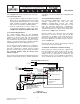
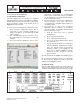
Refer to Figure 2.1 for terminal box connection
locations.
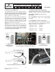
2.2.1 Current Sensing Module
All Copeland Discus compressors with CoreSense
Diagnostics use a current sensing module in the
terminal box. One of the motor power leads passes
through the “toroid” (current sensor). Information from
the current sensor is used to determine running amps,
power consumption and locked rotor conditions.
There are 3 voltage sensing leads attached to the motor
terminals and connected to the sensor module. Two
of the leads are white, and one is black. For proper
calculation of power factor and motor power it is
necessary for the black voltage sensing lead and
the power lead through the current sensor to be
connected to the same motor terminal.
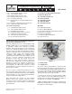
Figure 2.1 – Terminal Box Connections
24v AC Class II
Power Supply
Crank Case
Heater Power
Motor Power
Contactor Output to
Control Contactor