
Specifications

7
© 2012 Emerson Climate Technologies, Inc.
Printed in the U.S.A.
AE8-1368 R2
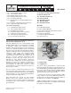
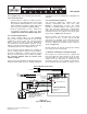
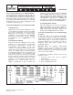
Refer to Figure 2.2 for sensor module lead connections.
2.2.2 Fan Connections
• Copeland Discus compressors with CoreSense
Diagnostics are not shipped from the factory with
fans installed. OEM installation of fans should
follow established regulatory, OEM engineering
and end user specifi cations regarding wiring.
• Head fan requirements for these compressors
are identical to other Discus compressors. Refer
to Application Engineering Bulletin AE4-1135.
2.3 Controller Requirements
The control network utilizes an open MODBUS
protocol. Rack controller manufacturers may develop
equipment to interface with and control Copeland
Discus compressors with CoreSense Diagnostics.
For Non-Emerson Retail Solutions products, consult
with the controller manufacturer regarding controller
compatibility with CoreSense Diagnostics v2.11.
For the Emerson Retail Solutions E2 controller, it
must be equipped with an Emerson Retail Solutions
CoreSense Diagnostics Network Interface Board
(Emerson Retail Solutions part number 637-4890).
The controller fi rmware must be revision level
2.60F01 or higher.
Refer to Emerson Retail Solutions E2 RX Refrigeration
Controller manual 026-1610 for detailed information
regarding the CoreSense Diagnostics compatible rack
controller.
2.4 Communications Network
The CoreSense Diagnostics module and rack
controller communicate with each other using
MODBUS communications protocol. The wiring
network uses RS485 hardware connections at each
node. The CoreSense Diagnostics communication
cable terminates in the rack controller at an interface
card and is routed to each compressor in a daisy-chain
format. Refer to Figures 2.5, 2.6 and 2.7.
One E2 controller can control two racks. One daisy
chain may be used for 2 racks, but two RS-485
connections are available on the Network Interface
Board if two parallel daisy-chains are preferred. The
CoreSense Diagnostics Network Interface Board is
shown on Figure 2.6
One E2 controller can control 4 suction groups, with up
to 16 stages in each suction group.
2.5 Network Terminations and Cable Routing
Each compressor (network node) has a jumper that
must be positioned to defi ne whether or not the node
is in the middle or end of the daisy-chain. The last
compressor in the daisy-chain is “terminated” and
the jumpers must be set accordingly. The E2 jumpers
on the Network Interface Board are always set for
L1
L2
L3
BLACK
WHITE
WHITE
CT
CONTROL
MODULE
COMM
24
VAC
IN
24
VAC
OUT
CCH
POWER
VOLTAGE SENSING LEAD
CCH
T1
T2
T3
L1
L3L2
CURRENT SENSING L1
POWER LEAD
Terminal Plate
or Fusite
Input VAC 24 VAC Class II Output
SENSOR MODULE
Crank Case Heater
Power Supply
(115 or 230 VAC)
(From harness in terminal box)
Black
White
To
Contactor
or Pilot
Relay
Important! Black Voltage Sensing
Lead Connected to Same
Terminal as Current Sensor
Power Lead
Figure 2.2
Sensor Module Wiring
Sensor Module Connections