
Specifications

8
© 2012 Emerson Climate Technologies, Inc.
Printed in the U.S.A.
AE8-1368 R2
“terminated” (refer to Figure 2.6).
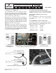
The communications wire to the compressor may be
routed into the rear of the side conduit (2D / 3D) and
along the channel which leads into the control module.
The 4D and 6D wire routing can be alongside the wire
harness and into the control module.
Appropriate use of strain reliefs will prevent damage to
the circuit board connector in the event of an accidental
mechanical load to the communication wire. Note that
the rear of the 2D / 3D conduit contains a tie-wrap
feature for anchoring the communication wire. Refer to
Figure 2.9 for photos of wire routing.
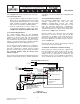
Important ! Note that the RS485 is polarity sensitive.
“Pos” wires must connect to other “Pos” terminals, and
“Neg” wires must connect to other “Neg” terminals.
The shield wire is connected to the center terminal,
or “0 volt” position. Refer to Section 6.15 for voltage
specifi cations and troubleshooting.
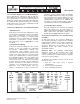
Figure 2.8
Communication Wiring and Jumper Positions
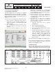
Figure 2.9
2D / 3D Communication Wire Routing
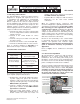
Figure 2.6
CoreSense Diagnostics Network Interface Board
Figure 2.7
Two Rack Daisy-Chain
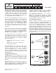
Figure 2.5
RS-485 Daisy-Chain
Confi guration
2.5.1 RS485 Communication Wiring Types
A shielded, twisted pair cable such as Belden #8761
(22AWG) should be used for the communication wiring.
2.6 CoreSense Diagnostics v2.11 Service
Instructions
Refer to Sections 3, 4, 6 and 7 of this document
for commissioning, service and troubleshooting
instructions.
2.7 Compatibility of Service Compressors
The following S/Ns may be used to determine whether
service compressors are compatible with CoreSense
Diagnostics hardware and accessories:
2D built on or after S/N 04D
3D built on or after S/N 04D
4D built on or after S/N 05D
6D built on or after S/N 05D