
Specifications

9
© 2012 Emerson Climate Technologies, Inc.
Printed in the U.S.A.
AE8-1368 R2
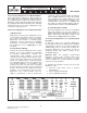
2.8 CoreSense Diagnostics v2.11 Model Numbers
Factory built Discus compressors with an S/E (the
last 3 digits in the model number) beginning with “A”
are Copeland Discus compressors with CoreSense
Diagnostics. Models with an S/E that begins with "AD"
are equipped with Demand Cooling. The remaining
numbers defi ne the service valve confi guration as well
as crankcase heater presence.
3.0 CoreSense Diagnostics v2.11 Quick Start Guide
1) Module Power
Apply power to the CoreSense Diagnostics v2.11
sensor modules located in the compressor terminal
box. Power requirements for the CoreSense
Diagnostics v2.11 modules is a 24VAC supply
provided by a class II transformer. For additional
information on transformer selection including
VA requirements refer to Appendix C of this
document.
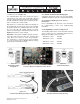
2) Communication Wiring
Connect the CoreSense Diagnostics v2.11 control
modules to the rack controller by confi guring
the RS-485 communications network. The
communication cable terminates in the rack
controller on the Network Interface Board, and is
routed to each of the compressors in a daisy-chain
format. For communications to function properly
the termination jumpers at the rack controller and
each module should be set according to their
position in the chain. The end devices (including
the rack controller) should be set to the terminated
position. The devices in the middle of the chain
should be set to unterminated. The CoreSense
Diagnostics v2.11 control modules have the
ability to communicate to E2 or non-E2 rack
controllers. Set the controller jumper accordingly.
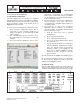
Refer to Figure 3.0 below to locate the position
of the termination and controller jumpers on each
control module. For a complete description of the
communications network refer to Section 2.4.
For details on troubleshooting problems with the
communications network refer to Section 6.15.
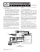
3) Verify DIP-Switch Settings
CoreSense Diagnostics v2.11 devices are equipped
with a DIP switch to set the node address. In
addition, this DIP switch determines the baud rate,
parity, control mode, and failsafe settings of the
module. Refer to Figure 3.0 below for details:
4.0 CoreSense Diagnostics v2.11 Commissioning
Procedure
As with other devices, the CoreSense Diagnostics
v2.11 modules must fi rst be commissioned to establish
communications with the rack controller. During the
commissioning process the E2 will recognize the
CoreSense Diagnostics v2.11 modules in order as
designated by the node address settings on the
module DIP switches.
Important Note: The following commissioning
instructions pertain to E2 controllers with version
3.02F01 or later fi rmware. If you have an earlier
version of fi rmware we recommend that you upgrade
to the latest version available.
To determine the fi rmware revision level in the E2
follow these steps:
1. From the main menu select 7 (System
Confi guration)
2. Press 3 (System Information)
3. Press 4 (Firmware Revision)
Figure 3.0 – Control Module Instruction Label