User Manual FP Series UPS 1000VA-3200VA www.allis.com.
FP series user manual Contents Safety information ..........................................................................................................I Limited product warranty and policy ................................................................................II 1. Presentation.............................................................................................................. 1 1.1 General description...................................................................................
FP series user manual Contents 4. Maintenance ........................................................................................................... 4.1 General Maintenance ....................................................................................... • Environment ........................................................................................... • Storing the UPS and battery ..................................................................... • When to replace the battery.........
FP series user manual Safety information SAVE THESE INSTRUCTIONS. This UPS unit operates from utility power and contains a number of high current back-up batteries, the information is important to all personnel involved. Please read this manual first before unpacking, installation and operation of the UPS.
FP series user manual Limited product warranty and policy Limited Product WarrantyAEC warrants this equipment, when properly applied and operated within specified conditions, against faulty materials or workmanship for a period of 24 months after the date of purchase. For equipment located outside Taiwan, AEC only covers faulty parts. AEC products repaired or replaced pursuant to this warranty shall be warranted for the unexpired portion of the warranty applying to the original product.
FP series user manual 1. Presentation 1.1 General description In today’s world where power requirements are increasing, utility power quality and reliability is decreasing. Normal everyday routines are constantly exposed to power problems such as power outages, sags, or surges. Any of these problems can spell disaster for the unprepared. Down time resulting form power problems costs industries billions of dollars over the course of a year.
FP series user manual 1. Presentation 1.2 System configurations 1.2.1 Rack mount 2U (426 W × 88 H × 500 D mm) 4U (426 W × 176 H × 500 D mm) 8U (426 W × 352 H × 500 D mm) Allis Electric -2- Rev3.
FP series user manual 1. Presentation 1.2.2 Tower standalone 2U (88 W× × 426 H × 500 D mm) 4U (176 W× × 426 H × 500 D mm) 6U (264 W× × 426 H × 500 D mm) Allis Electric -3- Rev3.
FP series user manual 1. Presentation 1.2.3 Single voltage battery design Battery Pack(BP) The 48VDC standard battery pack contains four 4 × 12V7AH lead-sealed acid batteries. It is used in all FP series UPS models and is interchangeable with each other. Battery Modules(BM) The battery module contains two(2) Battery Packs. The standard 2U high single module design always for easy configuration when adding extra battery modules for extended backup times.
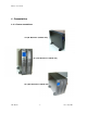
FP series user manual 1. Presentation 1.3 Front panel FP1000/FP1500/FP1600 1. 2. 3. 4. 5 1 2 3 4 Vent Push Buttons Graphic LCD Display Input Breaker Switch • FP1000: 15A 125V (UL) or 10A 250V (CE) • FP1500: 15A 125V (UL) • FP1600: 10A 250V (CE) 5. Internal 48VDC Battery Pack FP2200/FP2500/FP3200 1. 2. 3. 4. Vent Push Buttons Graphic LCD Display Input Breaker Switch • FP2200: 20A 125V (UL) • FP2500: 15A 250V (CE) • FP3200: 20A 250V (CE) 5.
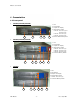
FP series user manual 1. Presentation 1.4 Rear panel FP 1000/ FP1500/ FP 2200/ FP 3000 (UL) FP1000/FP1500 8 1 1. 2. 3. 4. 2 2 Input Receptacle (15A 125V) Fan Optional Communication Slot Standard RS232 3 4 5 6 7 5. Battery Connector 6. Output Fuse (15A 250V) 7. Output Receptacle (NEMA 5-15R) 8. Input cable 6’ (10A 250V) FP2200 1 1. 2. 3. 4.
FP series user manual 1. Presentation FP3000 1 1. 2. 3. 4. 5. 2 3 4 5 6 Power Cord 6’ (NEMA L5-30P; 30A 125V) Output Fuse (15A 250V) Output Receptacles (NEMA (1)5-15R; (1)L5-30R) Optional Communications Slot Standard RS232 7 8 9 6. Battery Circuit Breaker 7. Fan 8. Battery Connector 9. Battery Cable FP1000/ FP1600/ FP2500/ FP3200 (CE) FP1000/ FP1600 Australian 8 British 8 French & German 1 2 3 4 5 6 7 8 1. 2. 3. 4.
FP series user manual 1. Presentation Output Receptacle options for FP1000/ FP1600. 1.IEC TYPE 2. EUROPE TYPE FRENCH BRITISH 5 6 GERMAN AUSTRALIAN FP2500/ FP3200 Australian 10 British 10 French & German 10 1 1. 2. 3. 4. 5. 2 3 Input Receptacle (15A 250V) Output Fuse (15A 250A) Output Receptacles (refer to Optional Communication Slot Standard RS232 4 ) 7 8 6. Battery Circuit Breaker 7. Fan 8. Battery Connector 9. Battery Cable 10.
FP series user manual 1. Presentation Extended Battery Module How to plug in the battery connector ? Before plugging in battery connector, please make sure the UPS unit is off. This is a critical action to ensure the safety of the installer. How to add on the additional BM or BMc ? 1 3 2 1. Battery Connector 2. Standard Battery Cable 3. Additional Battery Cable Allis Electric -9- Rev3.
FP series user manual 2. Installation 2.1 Unpacking The FP-Series UPS can be supplied in a number of boxes depending upon the model ordered. The number of boxes should be as follows: MODEL (Box 1) BATTERY MODULE (Box 2) FP1000/FP1500/FP1600 N/A (internal battery pack) FP2200/FP2500/FP3000/FP3200 1 Battery Module TOTAL BOXES 1 Box 2 Boxes The UPS and its shipping box are both labeled with the same bar code and serial number.
FP series user manual 2. Installation FP1000/FP1500/FP1600 Shipping Box 1 4 2 3 5 Mounting- feet × 2 6 Rack-mount × 2 7 Shipping Box Includes: 1. UPS 2. RS-232 communications cable 3. Cruiser software installation CD 4. User Manual (CD) 5. 2pcs mounting-feet for tower configuration 6. 2pcs 19” rack ears (+screws) for rack-mount configuration 7. Power Cord (for FP1000/FP1500/FP1600 only) Allis Electric - 11 - Rev3.
FP series user manual 2. Installation FP 2200/FP2500/FP3000/FP3200 Box 1 (Please refer to Shipping Box contents included in FP1000/FP1500/FP1600 previous page) Box 2 2 3 4 5 1 Box 2 Includes: 1. BM (or BMc) 2. 2pcs Extension link for tower configuration 3. 2pcs 19” rack ears (+screws) for rack-mount configuration 4. A steel link to connect the UPS and BM (or BMc) 5. Battery cable Allis Electric - 12 - Rev3.
FP series user manual 2. Installation 2.2 Installation in rack position Immovable The rack-mount ears WILL NOT support the weight of the UPS nor the battery module. They are used for mounting the UPS and battery module onto the rack. Mounting rails are required for each UPS or battery module. If rails are not installed on the rack, then please contact your service representative to order a rail kit. 1. Align the mounting ears and secure with the supplied screws. 2.
FP series user manual 2. Installation Removable Optional slide rails are available. Please contact your sales representative for more details. 1. Align the mounting ears and secure with the supplied screws. 2. Fasten the inner parts of the slide rails to the UPS or battery module with the screws provided. 3. Secure slide rails to posts. As a precaution , fixed mounting rails should be installation below the slide rails. 4. Slide the UPS or battery module into the slide rails. 5.
FP series user manual 2. Installation 2.3 Installation in tower position The mounting feet feature as flexibility in configuration and are able to add on the other Battery module using extendible links to meet long runtimes requirement. (3) (4) (2) (3) (1) (5) (4) (2) (3) (1) (2) (1) Allis Electric - 15 - Rev3.
FP series user manual 2. Installation 2.4 LCD orientation The graphic LCD display has been designed so that it can be easily oriented for tower or rack-mount configuration. Make sure that the UPS is shutdown before beginning. Ensure that the input breaker switch is in the OFF position. 1. Remove the top cover. 2. Detach the cables from the input breaker. 3. Remove the front panels. 4.
FP series user manual 2. Installation 2.5 Connection to communications 2.5.1 Connection Standard RS-232 Connection Optional USB Card Connection Allis Electric - 17 - Rev3.
FP series user manual 2. Installation 2.5.2 Standard RS-232 The UPS unit is supplied with a RS-232 cable to connect a local computer or modem to a remote computer installed with the “Cruiser” software. It can be used to monitor or control the UPS locally or remotely. Please refer to the chapter 3.5 Cruiser software or the Cruiser installation disk for details.
FP series user manual 2. Installation 2.5.3 Optional Interface Cards The spare communication slot can be used with optional interace cards such as DB9 Dry Contact Card, USB Card, AS400 Card, and SNMP/HTTP Card. 2.5.3.1 DB9 Dry Contact Card For Novell The DB9 Dry Contact Card offers three relay outputs for customwired application.
FP series user manual 2. Installation For Mechanical Dry Contact The DB9 Dry Contact Card offers three relay outputs for custom- wired application. The figure below shows the interface for the system connection: PIN Definition of DB9 for Mechanical Dry Contact interface PIN # of DB9 Function explanation BATTERY LOW - normally closed state, will become 1,2 open during active state. (PIN 2 is common) POWER FAILURE - normally open state, will become 3,5 closed during active state.
FP series user manual 2. Installation 2.5.3.3 AS400 Card FP-Series provide slot for AS/400 card. The AS/400 Integration of Lotus Notes is a blending of the administration, management, and security of the most popular business application system, the AS/400, with the world's leading messaging and groupware product, Lotus Notes. For more details about AS/400, please visit IBM’S website ”www.ibm.com” Allis Electric - 21 - Rev3.
FP series user manual 2. Installation 2.5.3.4 SNMP/HTTP Agent USHA Pro USHA ProE USHA (UPS SNMP and HTTP Agent) – USHA allows a user to obtain the status of and issue commands to the UPS. The UPS can be managed through the use of SNMP managers or Web browsers. USHA also provides shutdown programs for different operating systems. Shutdown commands can be sent for such events as power failure, low UPS battery condition, UPS overload, UPS overheating and scheduled shutdowns.
FP series user manual 2. Installation Net Agent Ⅱ (External) (Internal) NetAgent II allows a user to obtain the status of and issue commands to the UPS. It also provides other functions such as connecting to a modem to monitor the UPS when a permanent connection to the internet is not available.
FP series user manual 3. Operation 3.1 Display and Controls The diagram below show the basic functions of the front panel on all FP series UPS. FUNCTION/TEST LCD DISPLAY SET/ALARM SILENCE ON/OFF SYMBOLS USED ON GRAPHIC LCD DISPLAY INPUT BREAKER Alarm: When the UPS fails, the symbol will flash. Green Mode: When UPS is in Green Mode, the symbol will flash. Fault: When the UPS has failed and must be repaired, the symbol will flash.
FP series user manual 3. Operation CONTROLS INPUT BREAKER SWITCH • This switch disconnects the input power to the UPS. FUNCTION/TEST BUTTON This button has two functions: 1. Manual Battery Test • When the UPS is working under normal conditions, press this button to self-test the battery for 10 seconds. During this test, the battery will supply the UPS with power.
FP series user manual 3. Operation 3.2 Starting up/shutting down the UPS Normal Start-up of the UPS Step 1. Plug the UPS into an AC power source. Step 2. Turn on the Input Breaker switch. The UPS will begin its start-up process by first going into Bypass Mode and then into Normal Mode. After entering the Normal Mode, the UPS is ready for operation. Shutting down the UPS Step 1. Press ON/OFF key for one second. The UPS will switch to Bypass Mode. Step 2. Turn off the Input Breaker switch.
FP series user manual 3. Operation 3.3 Operating Modes NORMAL MODE During normal operation, utility power provides energy to the UPS. The UPS converts the utility power to computer-grade power for the connected loads. The UPS will also maintain the batteries at a fully charged state. All indicators are stable except Alarm. The graphic LCD display shows indicators of load, Inverter, PFC, Input power, Charger, Battery, Fan in medium speed, Green Mode, Fault, and Test.
FP series user manual 3. Operation BYPASS MODE In the event of a UPS overload or internal failure, an audible alarm will sound and the UPS will switch to Bypass Mode where utility power is powering directly to the connected loads. However, Battery Mode won’t occurs availably when the UPS: • Is overheating. • Has an overload condition of 101 to 110% for more than 120 seconds. • Has an overload condition of 111 to 150% for more than 20 seconds. • Has an overload condition greater than 150%.
FP series user manual 3. Operation 3.4 Configuration Settings Press the FUNCTION/TEST button and SET/ALARM SILENCE button at same time for one second. Alarm will sound one beep; the unit is in Configuration Mode. There are eight Bit columns at the bottom of the graphic LCD display. From left to right, they are identified as Bit 7 to Bit 0. When the UPS is in Configuration Mode, Bit 0 will be lit. Press the FUNCTION/TEST button to move between Bit 0 to Bit 6.
FP series user manual 3. Operation Output Voltage NEVER change the voltage settings when the UPS is ON and powering connected loads. 1. Press FUNCTION/TEST and SET/ALARM SILENCE buttons at the same time for one second. A short beep will signal that UPS is ready for configuration settings. 2. Press the Function/Test button until Bit0 or Bit 1 is lit. If the Bit0 and Bit1 are lit, then output voltage is 240V for FP1000/ FP1600/ FP2500/ FP3200 or Output voltage is 120V for FP1000/FP1600/FP2200/FP3000. 3.
FP series user manual 3. Operation 3.5 Cruiser Software Introduction The Cruiser software has been designed with user-friendly operating status & icons to be easier acknowledge and operation. Cruiser can send warning messages to a pager, via e-mail or over a LAN. thus providing an early warning system for power failures, system shutdown and a variety of other scenarios. It allows a faster response time, even when the user is not locally available.
FP series user manual 3. Operation Installation 1. Insert the Cruiser CD into the CD-ROM Drive. 2. The setup program will automatically run. If it does not, then simply double-click on the setup.exe file on the CD. (Note1) 3. Follow all the on-screen instructions. Step 1: Allis Electric Click Next to continue. - 32 - Rev3.
FP series user manual 3. Operation Step 2: Type in User Name and Company Name. Step 3: Type in the Serial Number. Allis Electric - 33 - Rev3.
FP series user manual 3. Operation Step 4: Choose the Destination Folder Step 5: Restart the computer. Allis Electric - 34 - Rev3.
FP series user manual 3. Operation Step6: After finishing the installation, the setup process will create the Cruiser program group in Programs Files and add its icon to System task bar. Right will pop up its program menu. click on Cruiser icon • • • • • • • Allis Electric Hide/Show Monitoring Window: This function is to hide/show the Cruiser's monitoring window. On-line Help File: This option is to launch the on-line help file which will help you to use Cruiser well.
FP series user manual 4. Maintenance 4.1 General Maintenance The FP-Series UPS requires very little maintenance. The batteries are sealed, valve-regulated, maintenance-free and enclosed in a fire-retardant pack. The batteries should be kept charged to maintain their designed lifetime. When utility power is supplied to the UPS, it will continuously charge the batteries. Environment For the best preventive maintenance, keep the area around the UPS clean and dust-free.
FP series user manual 4. Maintenance 4.2 Battery Pack Replacement With the hot-swappable battery pack design, the FP-Series UPS batteries can be easily replaced without turning off the UPS or disconnecting the load. The batteries can also be replaced by shutting down the UPS first. This is done by pressing the ON/OFF button for one second and letting the UPS switch to Bypass Mode; then turn off the Input Breaker switch and unplug the UPS. 1.
FP series user manual 4. Maintenance 4.3 Testing new batteries Start up the UPS with load added. Press the FUNCTION/TEST button for three seconds to activate the self-test. If the UPS switches back to Normal Mode after 10 seconds, then the batteries are good. If it does not, then please check the battery cable or connections. Contact your sales representative for assistance. 4.4 Recycling the used battery Do not discard the UPS, the battery pack, or batteries into the trash.
FP series user manual 5. Troubleshooting 5.1 Audible alarms and status Audible Alarms Possible Cause Three short beeps 1. Utility voltage error. Four short beeps 1. Utility frequency error. Five short beeps 1. UPS internal overheating. 2. Fan failure. Six short beeps 1. PFC over-current. Seven short beeps followed by three long beeps 1. Battery backup time running down. Long continuous beep 1. Output overload. 2. Charger failure. 3. UPS fault. Action 1.
FP series user manual 5. Troubleshooting 5.2 Troubleshooting Guide Problem Possible Cause UPS will not turn on 1. Input breaker switch is OFF. 2. UPS input breaker has tripped. 3. Input/battery cables not connected properly. UPS will not provide power to load 1. Power only present on one output receptacle. 2. No output from output receptacles. 3. Output fails as soon as load connected. 1. Input fuse blown. 2. Generator does not power the UPS.
FP series user manual 6. Appendix 6.1 Technical characteristics Design principle Components description Input filter This printed board assembly provides surge protection, certified by IEC 61000-4-5 and IEC 801-5, and filters both electro-magnetic interference (EMI) and radio frequency interference (RFI). It minimizes surges and interference present in the utility line and keeps sensitive equipment protected.
FP series user manual 6. Appendix Charger The battery charger uses the energy from the utility power and precisely regulates it to continuously charge the batteries by “constant power” mode. The batteries are charged whenever the FP-Series UPS is plugged into utility power. The charger will operate as long as the input voltage is over 60 VAC. DC/DC converter The DC/DC converter utilizes energy from the batteries and boosts up the DC voltage to the operating voltage for inverter.
FP series user manual 6. Appendix 6.2 Specifications General specifications The principal operating characteristics of the FP-Series UPS at 25°C ambient operating temperature is shown below. MODEL FP1000 FP1600 FP2500 FP3200 INPUT Input Voltage 230 V (160 ~ 276 V) (Nominal input voltage) Nominal input Frequency 50 / 60 Hz ±5 Hz Input PFC >0.
FP series user manual 6. Appendix MODEL FP1000 FP1500 FP2200 FP3000 INPUT Input Voltage 120 V (Nominal input voltage ) (80 ~ 138 V) Nominal input Frequency 50 / 60 Hz ±5 Hz Input PFC >0.98 @ full load OUTPUT Power 1000VA/700W 1500VA/1050W 2200VA/1540W 3000VA/2100W Output Voltage 100V / 110V / 115V / 120V (Output Voltage Regulation) (Rated Voltage ± 2% ) Output Frequency 50/60HZ (Auto-tracking) High Efficiency Mode >86% >86% >88% >88% (AC to AC) Output T.H.
FP series user manual 6. Appendix MODELS: FP1000-FP3200 CONTROL FRONT PANEL Buttons STANDBY, FUNCTION and SET Indications Fault, Charger, PFC, Green, Line, Booster, Inverter, Bypass, Load at 25/50/75/100%, Batteries at 25/50/75/100%. Audible Alarms DC Mode, Low Battery, Voltage Error, Frequency Error, Charger Failure, Overheating, Overload, Fault, PFC Overload.
FP series user manual 6.
FP series user manual 6. Appendix 6.3 Contact information Asia Allis Electric Co., Ltd. 12th F1., No.19-11, San-Chung Road, Nan Kang District, Taipei 115, Taiwan R.O.C. Tel:886-2-2655-3456 Fax:886-2-2655-2286~7 E-mail: sales@allis.com.tw http://www.allis.com.tw Sheen Asia Electronics Co., Ltd. 2F, Building A2, Beiwei Industrial Area, GETDD, Guangzhou, People's Republic of China, 510730 Tel:+86-20-8222 1370/1 Fax:+86-20-8222-1419 E-mail: sales@sheenasia.com http://www.sheenasia.