
User manual


FP series user manual
Allis Electric - 24 - Rev3. July 2005
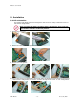
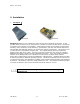
3. Operation
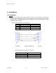
3.1 Display and Controls
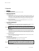
The diagram below show the basic functions of the front panel on all FP series UPS.
FUNCTION/TEST LCD DISPLAY
SET/ALARM SILENCE
ON/OFF INPUT BREAKER
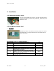
SYMBOLS USED ON GRAPHIC LCD DISPLAY
Alarm: When the UPS fails, the symbol will flash.
Green Mode: When UPS is in Green Mode, the symbol will flash.
Fault: When the UPS has failed and must be repaired, the symbol will flash.
Test: When UPS is conducting Battery Self-Test under Normal Mode, the symbol will
flash.
Load: The higher the load, the more bars will illuminate.
Inverter: When Inverter is normal, the symbol will illuminate.
Power Factor Corrector (PFC): When PFC is normal, the symbol will illuminate.
Input Power: When utility power is normal, the symbol will illuminate.
Charger: When charger is in normal operation, the symbol will illuminate.
Booster: When UPS starts Battery Booster, the symbol will illuminate.
Battery: The bars indicate an approximate amount of battery charge remaining.
Each bar represents 25% of battery capacity.
High–speed Fan: UPS is in Battery Mode.
Medium–speed Fan: UPS is in Normal Mode.
Low–speed Fan: UPS is in Bypass Mode.