
User manual


FP series user manual
Allis Electric - 25 - Rev3. July 2005
3. Operation
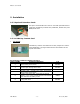
CONTROLS
INPUT BREAKER SWITCH
• This switch disconnects the input power to the UPS.
FUNCTION/TEST BUTTON
This button has two functions:
1. Manual Battery Test
• When the UPS is working under normal conditions, press this button to self-test the
battery for 10 seconds. During this test, the battery will supply the UPS with power.
If the battery are supplying unstable voltages, then the audible alarm will produce
one long beep and the UPS will switch to receiving power from the utility source.
2. Configuration UPS Settings
• When pressed together with the SET/ALARM SILENCE button for three seconds,
allows the user to configure UPS settings.
SET/ALARM SILENCE BUTTON.
This button has three functions
1. Silence Alarms
• Press this button for one second and the alarms will be silenced. After the alarm is
silenced, the UPS cannot audibly alert users of any additional problems.
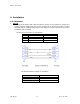
2. Change Selection
• Pressing the button for second will allow the user to view various parameters and
measurements including Input Voltage, Output Voltage, Output Frequency, Battery
Voltage, percent of Load, percent of Input current, Internal Temperature of the unit,
and Output Current.
3. Configuration Settings
• When pressed together with the FUNCTION/TEST button for three seconds, allows
the user to configure UPS settings.
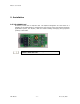
ON/OFF BUTTON.
This button controls output power to the load and has two functions:
1. Force UPS into Bypass Mode.
2. Start UPS from battery when utility power in not available.
When the UPS is in Normal Mode operation, pressing the ON/OFF button
once will put UPS into Bypass Mode. Pressing this button again will force
the UPS back to Normal Mode. If utility power is not available and UPS is
not connect with higher than 3% load, then the UPS will shut down after
30-40 seconds.
Overheating, PFC Over-current, Inverter over-current, Overload, Battery
mode, Low battery in battery mode, and charger failure alarms cannot be
silenced.