
User manual


FP series user manual
Allis Electric - 29 - Rev3. July 2005
3. Operation
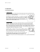
3.4 Configuration Settings
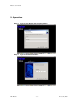
Press the FUNCTION/TEST button and SET/ALARM SILENCE button at same time
for one second. Alarm will sound one beep; the unit is in Configuration Mode.
There are eight Bit columns at the bottom of the graphic LCD
display. From left to right, they are identified as Bit 7 to Bit 0.
When the UPS is in Configuration Mode, Bit 0 will be lit. Press the
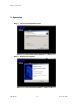
FUNCTION/TEST button to move between Bit 0 to Bit 6. When
changing from Bit 0 to Bit 6, check to see if Bit 7 is lit. If it is, then
that located Bit is set. Pressing the SET/ALARM SILENCE button
will toggle between set and unset.
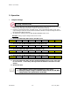
Bit Definition Table
Key Button
Setting
Bit Definition
SET/A
larm
Button
Status Setting
Bit 7
On=lit Off=unlit
Green Mode Bit 3
On: Disable Green Mode
Off: Enable Green Mode
Output
Voltage
208V
(100V)
220V
(110V)
230V
(115V)
240V
(120V)
Bit 1 Off Off On On
Function
Button
UPS INVERTER
OUTPUT
VOLTAGE
Bit 0 Off On Off
On
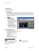
Green Mode
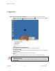
Enable/Disable Green Mode
1. Pressing the FUNCTION/TEST and SET/ALARM SILENCE buttons at the same time for 1
second. Alarm will sound one beep; the UPS is in configuration mode .
2. Press the FUNCTION/TEST button until Bit 3 is lit. If Bit 7 is lit, then Green Mode is
disabled. If Bit 7 is unlit, then Green Mode is enabled.
3. To change the setting, press the SET/ALARM SILENCE button once.
4. After changing to the desired setting, press the FUNCTION/TEST and SET/ALARM
SILENCE buttons at same time for one second. An audible beep will sound and the Green
Mode setting is set.
Bit 7 Bit 6 Bit 5 Bit 4 Bit 3 Bit 2 Bit 1 Bit 0