
User manual
FP series user manual
Allis Electric - 42 - Rev3. July 2005
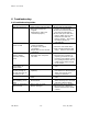
6. Appendix
Charger
The battery charger uses the energy from the utility power and precisely regulates it to
continuously charge the batteries by “constant power” mode. The batteries are charged
whenever the FP-Series UPS is plugged into utility power. The charger will operate as
long as the input voltage is over 60 VAC.
DC/DC converter
The DC/DC converter utilizes energy from the batteries and boosts up the DC voltage to
the operating voltage for inverter. This allows the inverter to operate continuously at
optimum efficiency and voltage.
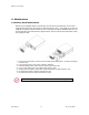
Battery
The FP-Series UPS utilizes a flame-retardant battery pack comprised of four 12V 7AH,
valve-regulated, and sealed lead acid batteries. All FP battery packs are interchangeable
and are easy to install or change. To maintain battery life, the UPS should operate in an
ambient temperature of 68°F to 77°F (20°C to 25°C). Battery modules containing two
battery packs are available for extended battery run times.
Transfer switch
The FP-Series UPS provides an alternate path to energize the connected load. If the
UPS has an overload, over input current, over crest-factor load (designed for 3:1
nonlinear loads), failure condition, or is overheating, then it will automatically switch so
that power is being supplied by the utility power. When this occurs, an audible alarm will
sound and a visual indication will be shown on the LCD display.
Output filter
This filter prevents electro-magnetic conductance (EMC) leakage and RFI noise to output.
It minimizes interference present in the inverter and utility line to keep sensitive
equipment protect.